Eyeon:Manual/Fusion 6/Color Curves
From VFXPedia
[ Main Manual Page ]
Contents |
Controls
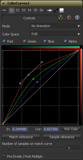
The Mode options changes between animated and dissolve modes. The default mode is static, where adjustments to the curves are static. Setting the Mode provides a change spline for each channel, allowing the color curve to be animated over time.
Dissolve mode is essentially obsolete and is included for compatibility reasons only.
The splines in the LUT view can represent color channels from a variety of Color Spaces. The default is Red, Green and Blue. The options in this menu allow an alternate color space to be selected. A detailed description of the color spaces available here can be found in the online reference documentation for the Color Space tool.
Use the Color Channel controls to select which channel's spline is currently active for editing. The labels of these controls will change to reflect the names of the channels for the current color space. Normally, they will read as Red, Green and Blue. If the color curves tool is operating in YUV color space, they will read as Y, U and V instead.
These controls do not restrict the affect of the tool to a specific channel. They only select whether the spline for that channel is editable. These controls are most often used to ensure that adding or moving points on one channel's spline does not unintentionally affect a different channel's spline.
The Spline Window shows the curves for the individual channels. It is basically a miniature spline editor. In fact, the curves shown in this window can also be found and edited in the spline editor.
The spline window is a complex control with many options. For a detailed description of how it works, please consult the Tool Controls chapter of the manual.
Use the In and Out controls to manipulate the precise values of a selected point. To change a value, select a point and enter the in/out values desired.
Click on the Pick button and select a color from an image in the display to automatically set keypoints on the spline for the selected color. The new points will be drawn with a triangular shape and can only be moved vertically (if point is locked, only the out value can change).
Points are only added to enabled splines. To add points only on a specific channel, disable the other channels before making the selection.
One use for this technique is white balancing an image. Use the Pick control to select a pixel from the image that should be pure grey. Adjust the points that appear so that the Out value is 0.5 to change the pixel colors to grey.
Use the context menu's Locked Pick Points option to unlock points created using the Pick option, converting them into normal points.
Clicking on the Match Reference button will automatically set points on the curve to match an image provided in the second (reference) input of the color curves tool.
This slider determines how many points are used to match the curve to the range in the reference image.
Selecting this checkbox will cause the image's pixel values to be divided by the alpha values prior to the color correction, and then re-multiplied by the alpha value after the correction. This helps to avoid the creation of illegally additive images, particularly around the edges of a blue/green key or when working with 3D rendered objects.
Tips for Color Curves (edit)
- Clicking the Sample Reference button (introduced in Fusion 6.1) will sample the center scanline of the background image and create a LUT of its color values.
- Fusion 6.2 added a match rectangle to the ColorCorrector and ColorCurves. Use it to crop the main input/background during colour matching.
| The contents of this page are copyright by eyeon Software. |

