Eyeon:Manual/Fusion 6/Display Views/The 3D View
From VFXPedia
[ Main Manual Page ]
- Introduction
- Types of Display Views
- Context Menu
- Displaying an Image
- Position and Layout
- Panning and Scaling the Image
- Previews
- Onscreen Controls
- Toolbars
- A and B Buffers
- Subviews
- View Types
- Choosing Color Channels
- The 3D View
- Quad Display Mode
- Effects Masks
- Guides
- Look Up Tables (LUTS)
- View Options and Preferences
- Status Bar Information
- General Display Options
- Display View Label
Contents |
The 3D View
The 3D View is only available when viewing a tool from Fusion's 3D category of tools or viewing some particle systems. It shows a representation of a composite in a true OpenGL-accelerated 3D environment. This chapter is closely related to the Working in 3D chapter of this manual.
Rotating, Panning And Scaling The View
For the most part, navigation in the 3D environment is identical to the navigation of 2D Images in the view. Panning and zooming the view are identical. To rotate in the view, hold the Alt key down and click-drag left or right with the middle mouse button. Alternatively, hold down the middle and right mouse buttons together while dragging horizontally.
Wireframe
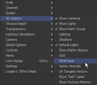
The Wireframe view shows not only 2D Images on image planes, it also shows true geometry, such as that generated by the particle system, text tool, FBX mesh import and basic primitives from the 3D toolset. To display these elements in wireframe rather than shaded mode, click the Wire button in the view toolbar or select 3D Options>Wireframe from the view's context menu.
Changing 3D Viewpoints
By default, the 3D view shows a free perspective camera to get a look at the 3D scene from any angle. Change the view to look through a camera in the scene, a spotlight, or any of the usual orthographic views.
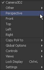
To change the 3D Viewpoints, right-click in the view and select the Camera submenu from the context menu. The choices include Perspective, Front, Top, Left and Right.
If one or more camera objects are present in the 3D environment, these will also be listed as options in this context menu. Spotlights and other lights or objects in the scene will be listed in the Other submenu. Selecting one of these will show the point of view of the camera, light or object chosen. While looking "through" an object in this manner, rotating, panning or zooming the view will instead change the rotation, position and scale of the camera, light or other object.
The "Copy PoV to" submenu is very useful for instantly positioning and orienting a camera, light or other object to match the current point of view shown in the Display View. Choosing an object from this submenu will copy the view's position and angle to the object's Translation and Rotation controls. Note that this is done in the object's own co-ordinate space; any transformations downstream of the object are not taken into account.
A small text label is usually drawn in the bottom corner of the view to indicate which of the available viewpoints is currently displayed. Right-clicking on this label or the axis control above it acts as a shortcut to the Camera submenu, allowing easy selection of cameras and other viewpoints.
Lighting
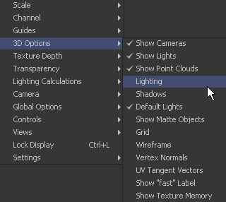
A default 3D view has Lighting turned off. Enable the display of lighting by clicking on the Light button in the view toolbar, or by right-clicking and selecting Lighting from the 3D Options sub context menu.
If there are no lights in the scene, default lighting will be used (Note: Prior to Fusion 5.1, no defaults lights are used and all textures will be dark). Adding a light to the scene will disable the default lighting, as will unticking the Default Lights option.
To see the effects of a light upon the scene, view the Merge3D tool that combines the light and the scene, or a tool downstream from this. Viewing just the light tool by itself will show only an empty scene, with nothing to be illuminated.
Shadows
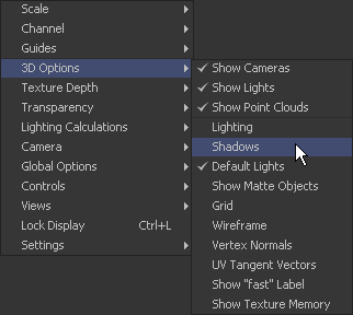
A default 3D view has Shadows turned off. To see shadows in the interactive OpenGL view, enable them by clicking on the toolbar button labelled Shad, or by right-clicking and selecting Shadows from the 3D Options sub context menu.
Enabling shadows will automatically turn on lighting, if this feature is not already turned on.
Transparency
A default 3D view uses a method of hiding obscured pixels known as Z-Buffering. This method is extremely fast, however it may in some cases produce inaccurate results when displaying transparent pixels, particularly when there is more than one layer of transparency in the scene.
An alternative is the Sorted method. This method can be significantly slower in some scenes, but provides accurate results no matter how many layers of transparency are in the scene.
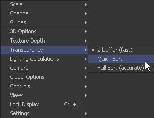
Change between the two transparency sorting methods by clicking the button labelled Fast in the view toolbar on or off, or selecting one of the options from the Transparency sub context menu.
Grid
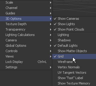
By default, the 3D view shows a Grid that is 24 x 24 units in size, centered on the origin at (0,0,0), and subdivided into large squares of 2 units and small squares of 0.25 units each. The grid is used to help provide a point of reference in the 3D scene. To disable the display of the grid, right-click and select Grid from the 3D Options sub context menu.
Vertex Normals
To display the normals for geometry in the scene, right-click in the view and select 3D Options>Vertex Normals from the context menu that appears. Normals indicate what direction each face of the geometry is facing, and they are used when calculating lighting and texturing on an object.
| The contents of this page are copyright by eyeon Software. |
