Eyeon:Manual/Fusion 6/Display Views
From VFXPedia
[ Main Manual Page ]
Display View Introduction
The Display Views are used to view the output of tools in the compositions. Generally these will be either images or 3D scenes, although the display views also support Flipbook previews, sequence and movie playback and 3D materials. Each display view can display the output of at least one tool in the composition.
Display views also offer the power to analyze images using waveforms, histograms and vectorscopes.
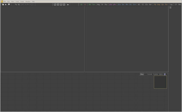
By default, Fusion opens with two display views visible side by side across the top of the program interface. Additional floating display views can be created, or an external video monitor can be used if supported hardware is present on the workstation, such as one of the board's manufactured by Digital Voodoo or Leitch.
The display views are OpenGL-accelerated and rely upon the presence of a good OpenGL-accelerated display device. For a list of supported video cards, visit www.eyeonline.com and check the support section of the website.
Left/Right Display Views
The primary display regions in Fusion are the Left and Right Display Views. Located immediately above the flow, timeline and spline regions, these display views are always available for use.
Floating Display Views
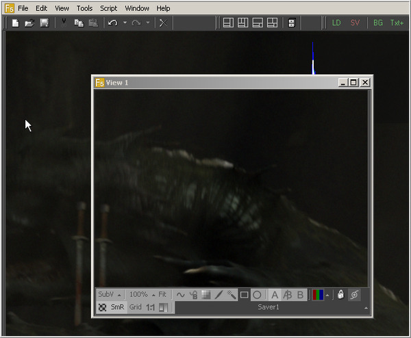
In addition to the large display views above the flow, an unlimited number of Floating Display Views can be created. These floating views are excellent for taking full advantage of a dual monitor configuration. Floating views can also be set to full screen mode to make the best use of screen real estate.
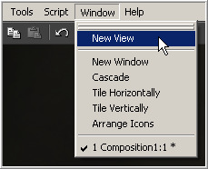
To create a new floating display view, select Window>New View from the menu bar at the top of the screen. The position and configuration of the new view can be saved in the layout preferences, if required.
Hardware Frame Buffers
When supported, or if video hardware is present in the computer, Fusion can take advantage of Hardware Frame Buffers to display images on an external NTSC, PAL or HD monitor.
The hardware display cannot be used to manipulate onscreen controls like center crosshairs or masks. They are extremely valuable for evaluating the images in the same format to which they will be output, and for determining color fidelity and accuracy with a properly-calibrated output monitor.
See the appendices at the end of this manual for a complete list of supported video I/O hardware.
Display View Types
Display View Context Menu
The display view provides a wide range of configuration options via a dynamic context menu that can be accessed by right-clicking in the view. Many of these options also have keyboard shortcuts or can be found in the view toolbar along the bottom of the view.
All of the options found in the Display View Context Menu are explained in depth throughout this chapter.
Displaying an Image in the Views
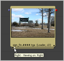
There are several methods to display the output of a tool in the display views. When a tool is displayed in one of the views, a status light appears on the left side of the tool's tile in the flow. To determine in what view the tool is displayed, hold the mouse pointer directly over the status light until a tooltip appears.
Generally, the leftmost indicator is for the left display view. The next one to the right is for the right display view. Additional indicators are used for floating views and video output devices.
The name of the currently-viewed tool is displayed on the horizontal toolbar at the bottom of the display view.
Viewing Images With Drag And Drop
- From The Flow View
- Click-drag any tool in the flow into a display view, then release the mouse button to display that tool's output.
- From The Tool Controls
- Click-drag the tool's control header from the control view on the left into a display view to display that tool's output.
- From The File Browser
- Drag and drop an image from the operating system's file browser into a display view to view that image. This will not add a tool into the flow. It is used only to rapidly preview an image before actually adding it to the flow.
Note: Holding down the Alt key while dragging an image tool into a display view will create a flipbook preview in that view instead. The Render Settings dialog will be displayed, and upon accepting the settings, the tool will be rendered and the resulting frames stored in RAM for fast playback on that view. This is similar to selecting Create Preview On from the tool's context menu. Hold down Shift+Alt instead to skip the dialog and immediately start rendering the preview with the last-used settings.
Viewing Images With The Context Menu
- From The Flow View
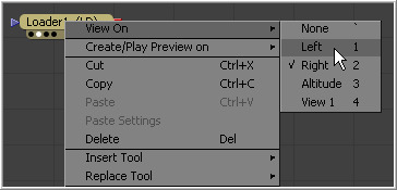
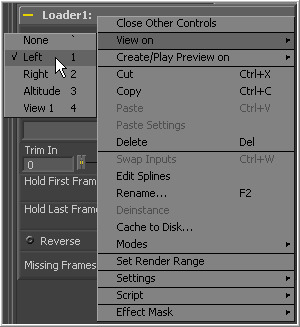
- Right-click on a tool's tile in the flow to display its context menu. Select View On, then choose the display view to use.
- From The Tool Controls
- Right-click on the tool's control header on the left to display the context menu for that tool. Select View On, then choose the display view to use.
- From The Timeline
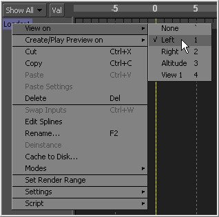
- Right-click on the tool's name in the tree menu to the left of the timeline to display the context menu for that tool. Select View On, then choose the the display view to use.
Viewing Images With Keyboard Shortcuts
Each display view in Fusion is assigned a numeric shortcut between 1-9, which can be used to quickly display the result of the currently selected tool. The left display view is accessed by pressing `1'. The right display view is accessed with `2', and successive floating views or hardware frame buffers are assigned numbers in the order in which they are created.
To determine the shortcut assigned to a display view, bring up the View On menu in any tool's context menu. The shortcut assigned is displayed to the left of the tool's name in the menu. These shortcuts are available for use when the flow editor or the tool controls are active.
Note (5.1) As of Fusion 5.1, the numeric keypad may also be used for display view shortcuts, in addition to the numeric keys arranged horizontally above the keyboard.
Removing Images From The View
To remove all images from all display views in one action, press the tilde (`) key. This key is usually found to the left of the 1 key on American keyboards.
Viewing Images From Disk
Use the display views to show stills, videos or sequences, even if they have not been loaded into the composition using a loader. From the desired view, click the right mouse button and select Load Image from the context menu. This will open a file browser. Navigate to the folder with the footage or image to be viewed and click OK. Still images will be displayed on the view statically. For image sequences and multi-frame formats, the transport controls will appear in the bottom of the control area to play, review, and loop the sequence.
Viewing Images Using Other Methods
Each tool tile has a small strip along the bottom that shows a small white indicator for each view. The strip is generally not visible until the tool is displayed in a view, selected, or the mouse pointer is positioned over the tile.
By hovering the mouse pointer over an indicator, a small popup will identify the view associated with the indicator. Generally, the leftmost indicator is for the left display view. The next one to the right is for the right display view. Additional indicators are used for floating views and video output devices.
When the indicators are visible, click directly on them to display or remove the tool's output image from a display. A white indicator shows that the view is displaying the image, otherwise, the indicator is black.
Display View Position and Layout
It is possible to customize the layout and configuration of fixed views to suit the size of the desktop and monitor, or to match personal preferences.
Once the desired layout has been achieved, use the Grab Document Layout button in the Layout preferences to remember the layout for newly-created documents. The Grab Program Layout button will remember the size and position of any floating views, and enabling Create Floating Views checkbox will automatically create them again when Fusion starts up.
The current view layout is always saved with the comp. Turn off the Recall Layout switch in the Layout preferences to ignore the saved layout when opening a comp.
Layout Toolbar
The Layout Toolbar at the top of the interface (shown below) can be used to configure the display views to several preset layouts.
- First Button
- This option maximizes the left display view, aligning the tool controls with the top of the screen.
- Second Button
- This splits the available display region equally between the left and right display views, aligning the tool controls with the top of the screen.
- Third Button
- This fully maximizes the left display view, aligning the tool controls with the bottom of the display area.
- Fourth Button
- This fully maximizes the display region, splitting the left and right views equally. The tool controls stay aligned to the bottom of the display region.
Splitter Bars
The relative sizes of the left and right display views can be adjusted using the horizontal splitter bar between them.
Click-drag the splitter to increase or decrease the amount of space used by one display view. The adjacent display view will adjust to suit the new layout.
The amount of vertical space available for both display views can be adjusted by click-dragging on the horizontal scroll bar between the display region and the work region.
Fullscreen Floating Views
Floating views are not affected by the buttons in the layout toolbar. Adjust the size of a floating view using the usual method of click-dragging on the outside of the window border, or by double-clicking on the window's titlebar. Additionally, right-click in the display and set the floating view to Fullscreen from the context menu. The fullscreen option only appears once an image is present in the view.
Fullscreen Fixed Views
To maximize any fixed display view so it fills the screen, place the mouse pointer over the view and press the F4 keyboard shortcut. To restore a maximized view to its original settings press F4 again. This shortcut can also be used to maximize the workspace below the fixed views.
Panning and Scaling the Image
Panning
To pan in any display view, place the mouse pointer in the view and hold the middle mouse button down. Drag the mouse in the desired direction. If the mouse does not possess a middle mouse button, hold Ctrl+Shift and click-drag the view (with the left mouse button) for the same effect.
When viewing a 3D scene, panning will change the point of view (and thus the center point for scaling and rotation too). A combination of panning and rotation will allow you to move the point of view anywhere in the scene.
Note that zooming in will decrease the sensitivity of panning, to allow finer control when navigating around small images and scenes. Correspondingly, pan sensitivity will increase when zooming out. If you need to move the point of view faster, zoom out first or reset the scale with Ctrl+1.
Scaling
The following methods can be used to scale an image or 3D scene once it has been displayed in a view.
Note that there is a lower limit to the scale of a 3D scene. Continuing to zoom in past this limit will instead move ("dolly") the point of view forwards. The mouse wheel will move forward slowly, and the keyboard will move more quickly.
Using the Mouse
- Mouse Drag
- Place the mouse pointer over the view, then hold the middle and left mouse buttons down while dragging the mouse to the left and right to scale smoothly in and out. The scaling is centered around the starting position of the pointer.
- Mouse Click
- Place the mouse pointer over the view, then hold down the middle mouse button. While holding down the middle mouse button, click once on the left mouse button to increase the scale or the right button to decrease the scale by a fixed amount. The scaling is centered around the position of the pointer.
- Mouse Wheel
- Place the mouse pointer over the active view, hold down the Ctrl key, and roll the mouse wheel up or down. Each step on the wheel increases or decreases the scale by a fixed amount, centered around the pointer.
Using the Keyboard
- Keyboard
- To change the scale by a fixed value, press the + or - keys on the numeric keypad while the display view is active. Ctrl+1 will set the image or scene back to its default of 100% scale, and will recenter it as well. Ctrl+F will fit the image or scene into the visible region.
Using the Context Menu
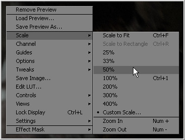
Press the right mouse button while the pointer is positioned over the display view and select Scale from the display view's context menu.
Using the View Toolbar
The scale button in the Display View Toolbar can also be used to adjust the scale of the view. Click anywhere on the scale button to bring up a menu of several preset scales to choose from, or click on the Fit button beside it to fit the image or scene to the view window.
Rotating
When viewing a 3D scene or 3D histogram, the display view can also be rotated. This can be done with the mouse.
Normally, view rotation "orbits" the point of view, to allow easy viewing from any angle. When viewing through a camera in the scene however, this changes to rotate (pitch and yaw) the camera instead.
Using the Mouse
- Mouse Drag
- Place the mouse pointer over the view, then hold the middle and right mouse buttons down (alternately, Alt key and middle button) while dragging the mouse to the left and right to rotate the view. The rotation is centered around the middle of the view.
Previews
In addition to displaying the output of a tool, the display views are also used to display flipbook previews and do file playback of image sequences and AVI or MOV files straight from disk.
RAM Flipbook Previews
RAM Flipbook Previews are preview renders that exist entirely within RAM. They are created by holding down the Alt key while dragging a tool into the display views, or by selecting Create>Play Preview from the tool context menus.
Once the preview is done rendering, the flipbook will be loaded into the view, temporarily overriding any tool currently displayed in the view. Playback controls appear in the bottom right corner of the interface beneath the tool controls, a Frame counter appears in the corner of the view, and a play/pause button is added to the right of the view's bottom toolbar.
To remove the preview and destroy the flipbook, right-click on the view and select Remove Preview.
Other options on the view's context menu allow enabling looped or ping-pong playback, or (as of Fusion 5.1) Fullscreen mode, which hides the rest of Fusion's interface. View controls are not displayed in Fullscreen mode. To exit Fullscreen mode, deselect it from the context menu, or press the Esc key.
It is also possible to "trim" the flipbook, to skip playback of the first or last few frames. This can be done using the scrub bar in the transport controls that appear at the bottom right of Fusion's window. Ctrl+drag the scrub bar to set or change the frames to be played, or right-click on it to set or reset the in & out points via a menu.
Mouse shortcuts
While the flipbook preview is showing, it can be played or scrubbed using only the mouse. These shortcuts work in Fullscreen mode as well.
- Playback
- Double-click the left mouse button anywhere in the view to start playback.
- Scrubbing
- Hold down the right mouse button and drag the mouse left or right to scrub through frames in the flipbook.
Keyboard shortcuts
While the flipbook preview is active, playback and frame advance can also be done with the keyboard. These shortcuts work in Fullscreen mode as well.
- Playback
- The spacebar can be used to start or stop playback. Hold down Shift while pressing the spacebar to play in reverse.
- Forward/reverse
- The left and right arrow keys will move the flipbook to the previous or next frame. Hold down Shift as well to jump back or forward 10 frames at a time. Ctrl+left will return to the first frame of the flipbook, while Ctrl+right jumps to the last frame.
File Sequence Previews
When a loader or saver is selected, the file sequence or footage loaded by that tool can be played back in the display view by pressing play on the transport controls that appear in the bottom of the tool controls region.
When the play button is selected, the file preview becomes active and Fusion will load the images as quickly as possible and play them to the display view. By default, the left display view is used for this purpose. That default can be changed using the Preview preferences. By changing these preferences, it is also possible to simultaneously play the file sequence to installed video hardware (this may decrease playback performance).
As with flipbooks, trimming in & out points can also be set for file sequence previews, using the scrub bar in the transport controls that appear at the bottom right of Fusion's window. Ctrl+drag the scrub bar to set or change the frames to be played, or right-click on it to set or reset the in & out points via a menu. By default, trimming done here while a Loader tool is selected will be mirrored in the Loader's Trim In/Out controls. This can be disabled using the scrub bar's context menu.
While the file sequence preview is enabled, normal viewing of tools to that display view is disabled. To return to normal operations, select another tool or blank area of the flow.
Onscreen Controls
The display views show Onscreen Controls, or widgets, for manipulating the controls of the currently selected tool. Common widgets include crosshairs, angle indicators, polylines and paint strokes. Each of these controls can be manipulated directly in the display view using the mouse or keyboard.
The display view shows the controls associated with the tools that are selected in the flow, timeline or spline editor. If multiple tools are selected, the controls for all of those tools are shown.
Note The controls shown are determined only by the tools that are selected, not by the tool displayed in the views. For example, a downstream blur is easily viewed while manipulating the controls for a selected polygon mask or merge.
Enabling/Disabling Onscreen Controls
The onscreen controls for a view can be disabled so that they do not interfere with viewing the image.
To disable the onscreen controls, click once on the Show Controls button in the view toolbar or select Show Controls in the Options submenu of the display view context menu. Alternately, use the Ctrl K keyboard shortcut.
Making Fine Adjustments To Controls
Adjusting a control with the mouse often lacks the precision required for fine work. In cases such as this, the keyboard can often be used to make small finite adjustments to the selected control.
The arrow keys can be used to adjust the position of the control along the vertical or horizontal axis by small steps.
Holding the Ctrl key down while using the arrow keys reduces the scale of each step by a factor of ten. Holding Shift down increases the scale of each step by a factor of ten.
Display View Toolbars
There are two toolbars in the display view; a horizontal view toolbar called the View Toolbar, and a vertical toolbar called the Tool Toolbar. Both are used for showing buttons that are specific to the selected control.
Display View Toolbar
The View Toolbar runs across the bottom of the view, providing access to many of the most commonly-used settings. Most of the buttons found on this toolbar are described in detail throughout this chapter.
This toolbar is dynamic. The buttons displayed may change depending on the type of viewer.
A 3D display view shows a set of buttons for controlling the display of lights and shadows, for example, but these buttons are missing from a 2D view since they would have no meaning in that context.
To learn more about a button's use, hold the mouse pointer over the button. A small popup will describe the button and its function.
Tool Specific Toolbars
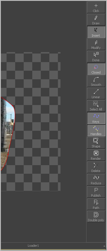
In addition to the toolbar displayed at the bottom of each view, Fusion also has a space reserved to the side of the view for Tool Specific Toolbars. Text, masks, paths, paint strokes and the 3D environment are some of the tools that make use of this toolbar.
Customize the size and type of buttons displayed in this toolbar using its context menu, accessed by right-clicking on the toolbar with the mouse.
Customizing The View Toolbars
Right-click on the toolbar to display its context menu. This menu is used to change the size of the icons used for the buttons, and also to determine whether text labels are used to represent the button's functions.
A and B Buffers
Each display view has two buffers for viewing images. Each buffer can be considered a complete and separate view. Generally, all that is seen the default A buffer.
Note Buffers can be set to different display view types. It is entirely possible to have an A buffer showing the image with a B buffer showing a histogram.
Switching Between Buffers
- Toolbar
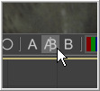
- Click on the view toolbar button labelled A or B to switch to the associated buffer.
- Keyboard
- Use the comma (,) key to set the active view to the A buffer, the period (.) key to set the view to the B buffer and the (/) key to enable the split wipe mode (described below).
- Split Wipe Images
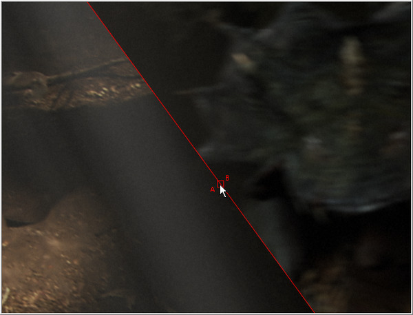
- The A|B buffers can be used to enable a split display, where the separate buffers are displayed onscreen simultaneously. The displays are separated by a red splitter bar, which can be adjusted in any direction or angle by click-dragging on the splitter.
To enable the Split Wipe, click on the A|B button.
Turn off the split wipe mode by switching to either the A or B buffer directly using the toolbars or keyboard shortcuts.
While split wipe is enabled, new tools can still be dragged and dropped into either buffer to change the image displayed. Panning or zooming either buffer will keep the other buffer in sync.
Different channels, view LUTs or other display options can be selected for each buffer individually. This allows easy comparison of channels, LUTs etc while in split wipe mode, or by quickly switching between the A and B buffers with the hotkeys.
Occasionally, you will have either zoomed in or panned so far from the splitter that it will be no longer visible in the view. Holding down Ctrl+Alt and clicking anywhere in the image will cause the splitter to jump to the current mouse position.
Holding down Shift while dragging the splitter bar will "snap" it to the nearest 45 degree angle.
Subviews
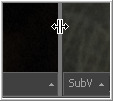
A Subview is a smaller display view that docks within the main view. It is connected to the same tool as the main view and is often used to show somewhat different information about the image.
For example, the RGB channels may be viewed in the main view, with the alpha channels in a subview. Any of the view types mentioned above can be used in a subview. In fact, several view types are designed for use only in the subview.
For the most part, the subview is nothing more than a miniature view, with its own context menu and options. It responds to the same keyboard shortcuts and navigation controls as any other display view.
Displaying/Hiding The Subview
Use the V key to toggle the subview on and off in the active view. Alternately, click on the subview button in the view toolbar, or select Views>Subview>Enabled from the context menu.
Changing The Subview Type
To change the subview type, click on the small arrow next to the Subview button in the display view toolbar. This will show a popup menu of all available subview types. Select one from the list or right-click in the subview and select the desired view type.
Swapping The Subview With The Main View
Use the Shift-V keyboard shortcut to swap the main view and the subview, or select Views>SubView>Swap from the context menu.
Note This is not always valid, as certain view types can only be used in the subview. In such cases, the swap will not take place.
View Types
As well as showing images, views can be changed to show a variety of different bits of information about the image. Not all views are valid at all times. For examples, the 3D viewer is not available for a 2D tool and many of the viewers are only valid for subviews.
Changing The View Type
To change the View Type, open the display view's context menu and select the desired type from the view's submenu.
2D Viewer
The 2D Viewer is the basic 2D display view for showing images. When used as a subview, a different tool than the one used in the main view can be displayed by dragging and dropping the tool into the subview. This is the only subview type that is not slaved, showing the same tool that is displayed in the main view.
3D Image Viewer
The 3D Image Viewer is the basic 3D display view, available when viewing a tool from the 3D category.
Histogram
The Histogram is an analysis tool that can be used to identify problems with contrast and the dynamic range in an image. This is essentially a graph that shows the frequency distribution of colors in the image. The horizontal axis shows the colors from black to white. The vertical axis shows the number of pixels in the image that occur at each level. Histograms are excellent tools for examining the overall contrast and distribution of colours in an image. As of Fusion 5.2, the Histogram viewer will also show out-of-range colours found in floating point images.
Tip: The Histogram viewer will also display Gradient information. Currently, the only tools in Fusion that can output Gradients are the From Image and Perturb modifiers. Drag the modifier's titlebar into the view to see the gradient represented as a histogram.
3D Histogram
This more advanced histogram type shows the color distribution in an image within a 3D cube. One advantage to 3D Histogram is that it can accurately represent the out-of-range colors commonly found in floating point and high dynamic range images. Navigate the 3D cube like any other 3D view (Alt-MMB to rotate).
Vectorscope
The Vectorscope duplicates the behavior of a specific type of video test equipment, displaying a circular graph that helps to visualize chrominance signals.
Waveform
The Waveform duplicates the behavior of a specific type of video test equipment, displaying a line or bar graph that helps to visualize the voltage, or luminance, of a broadcast signal.
Navigator
The Navigator can only be used in a subview. It provides a small overview of the entire image, with a rectangle that indicates the portion of the image that is actually visible in the main display view. This is useful when zooming in on an image in the main view.
Magnifier
The Magnifier can only be used in a subview. It shows a zoomed-in version of the pixels under the mouse pointer in the main view.
Image Info
The Image Info view can only be used in a subview. The image info tab shows a horizontal bar across the top of the image with information about the frame size, pixel aspect and color depth of the viewed image.
Color Inspector
The Color Inspector can only be used in a subview. The color inspector shows information about the color channels of the pixel under the mouse pointer. It will show all channels present, even the auxiliary channels such as Z buffer, XYZ normals and UV mapping channels.
The color is not sampled from a specific pixel, but rather it is sampled from several pixels. The default setting will sample from a 3 x 3 array of pixels around the mouse pointer. This can be changed by opening the View panel in the preferences and changing the value of the Color Picking Area Size.
Choosing Color Channels
Fusion's display views and subviews are not limited to displaying only the full color version of the image. The separate Color and Depth Channels that comprise the image can be viewed separately.
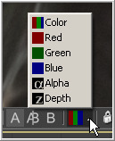
Use the Channel toolbar button (shown below), the view's context menu or keyboard shortcuts to change the channel displayed in a view.
Click the triangle on the side of the toolbar button to show the list of channels. Clicking elsewhere on the button will switch between Full RGB and Alpha, or the currently viewed channel.
The following hotkeys will also change the channel displayed in the active view:
- C - Full RGB color display
- R - Display Red channel
- G - Display Green channel
- B - Display Blue channel
- A - Display Alpha channel
- Z - Display Z-Buffer channel
Viewing Non Color Channels
The Fusion view has only support for the RGBA and Z channels. To view the auxiliary image data stored in RLA or OpenEXR files, it may first be necessary to copy the data from the auxiliary channel to one of the color channels using a channel boolean tool. Many auxilliary channels employ a 32 bit datatype, so ensure the image is processing at 32bit per channel before applying the channel boolean, or else the data may end up being incorrectly displayed.
The 3D View
The 3D View is only available when viewing a tool from Fusion's 3D category of tools or viewing some particle systems. It shows a representation of a composite in a true OpenGL-accelerated 3D environment.
Rotating, Panning And Scaling The View
For the most part, navigation in the 3D environment is identical to the navigation of 2D Images in the view. Panning and zooming the view are identical. To rotate in the view, hold the Alt key down and click-drag left or right with the middle mouse button. Alternatively, hold down the middle and right mouse buttons together while dragging horizontally.
Wireframe
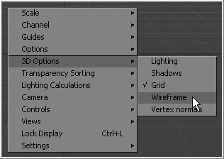
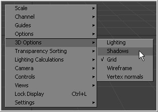
The Wireframe view shows not only 2D Images on image planes, it also shows true geometry, such as that generated by the particle system, text tool, FBX mesh import and basic primitives from the 3D toolset. To display these elements in wireframe rather than shaded mode, click the Wire button in the view toolbar or select 3D Options>Wireframe from the view's context menu.
Changing 3D Viewpoints
By default, the 3D view shows a free perspective camera to get a look at the 3D scene from any angle. Change the view to look through a camera in the scene, a spotlight, or any of the usual orthographic views.
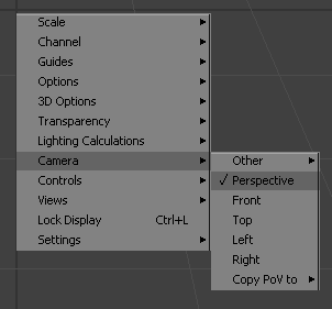
To change the 3D Viewpoints, right-click in the view and select the Camera submenu from the context menu. The choices include Perspective, Front, Top, Left and Right.
If one or more camera objects are present in the 3D environment, these will also be listed as options in this context menu. Spotlights and other lights or objects in the scene will be listed in the Other submenu. Selecting one of these will show the point of view of the camera, light or object chosen. While looking "through" an object in this manner, rotating, panning or zooming the view will instead change the rotation, position and scale of the camera, light or other object.
The "Copy PoV to" submenu is very useful for instantly positioning and orienting a camera, light or other object to match the current point of view shown in the Display View. Choosing an object from this submenu will copy the view's position and angle to the object's Translation and Rotation controls. Note that this is done in the object's own co-ordinate space; any transformations downstream of the object are not taken into account.
A small text label is usually drawn in the bottom corner of the view to indicate which of the available viewpoints is currently displayed. Right-clicking on this label or the axis control above it acts as a shortcut to the Camera submenu, allowing easy selection of cameras and other viewpoints.
Lighting
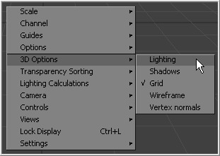
A default 3D view has Lighting turned off. Enable the display of lighting by clicking on the Light button in the view toolbar, or by right-clicking and selecting Lighting from the 3D Options sub context menu.
If there are no lights in the scene, default lighting will be used (Note: Prior to Fusion 5.1, no defaults lights are used and all textures will be dark). Adding a light to the scene will disable the default lighting, as will unticking the Default Lights option.
To see the effects of a light upon the scene, view the Merge3D tool that combines the light and the scene, or a tool downstream from this. Viewing just the light tool by itself will show only an empty scene, with nothing to be illuminated.
Shadows
A default 3D view has Shadows turned off. To see shadows in the interactive OpenGL view, enable them by clicking on the toolbar button labelled Shad, or by right-clicking and selecting Shadows from the 3D Options sub context menu.
Quad Display Mode
The display view generally only has one surface on which to show an image. It is possible to split the view into four parts. This is called a Quad View. This is most commonly used in conjunction with the 3D view to allow a view of the 3D environment from several different angles at one time.
Although there are four parts to the view, all four will be viewing the same image. When using a quad view to display a 3D environment, there is a choice between displaying the front, left, top, bottom and perspective orthographic views, as well as the view through any cameras or spotlights present in the scene.
When used with a 2D environment, each part can be used to show a different view type. For example, the image in one part can be shown while the other parts show the alpha channel, vectorscope and histogram.
Enabling And Disabling The Quad View
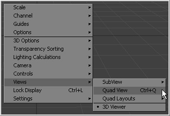
To toggle the display of the Quad View, select Views>Quad View from the display view's context menu or use the Ctrl-Q keyboard shortcut. A Quad button on the view toolbar is also seen when viewing a 3D environment.
Quad View Layouts
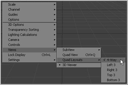
There are a variety of Quad View Layouts, ranging from four equally-sized panels to having three small panels across the bottom of a larger single panel.
To try the various layouts, toggle Quad View on, then select one of the choices found in the Views>Quad Layout's display view context menu.
Effects Masks
Fusion's Effect Masks are used to restrict the effect of a tool to a specified portion of an image. Masks can be polylines, basic primitive shapes, paint strokes or bitmaps from other tools.
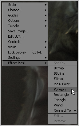
To add an effect mask to the currently displayed tool, click on the button for the desired type of mask in the view toolbar or right-click in the display view and select Effect Mask from the context menu.
The toolbar buttons can only be used to add effect masks. Garbage and pre- masks are added via the view's context menu.
For more information, see the Effect Masks chapter.
Guides
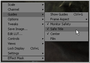
A number of standard Guides can be displayed in the views. The four guides are Monitor Safety, Safe Title, Center and Film.
Enabling And Disabling The Guides
- Context Menu
- Select Guides>Show Guides from the display view's context menu.
- Keyboard
- Use Ctrl-G to enable or disable the display of guides in the active view.
Selecting A Guide
- Monitor Safety
- This indicates the safe area viewable on most monitors and TV screens.
- Safe Title
- This indicates the safe area for titles viewable on all TV and monitor screens.
- Center
- This shows the Center point and X and Y axis of the view.
- Film
- This displays the Film guides as specified in the Frame Format>Preferences screen. Some frame format defaults have a corresponding default for the guides, whereas some will require customization.
Film Guide 1 contains four text boxes. These boxes specify the offset from the edges of the image for the Left Guide, Top Guide, Right Guide and Bottom Guide, in order. As with all offsets in Fusion, this is a resolution-independent number where 1 is the width of the full image and 0.5 is half the width of the image.
Film Guide 2's text box is used to set the aspect ratio of the projection area.
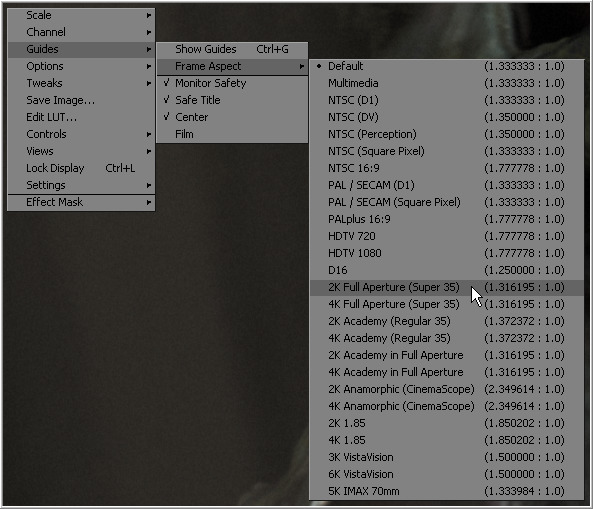
Guide Frame Aspect
The Guide Frame Aspect can be used to help show how the current image relates to a specified frame format. The frame aspect is usually set to Default. This forces the frame aspect to the same resolution as the image displayed in the view.
When the frame aspect is set using the Guides>Frame Aspect context menu, the guides will represent the exact boundaries of the specified format. The guides will display the correct frame format and any image area outside of that will be dark grey.
Look Up Tables (LUTS)
See the Look Up Tables chapter.
View Preferences and Settings
View Preferences
The default settings for each display view can be changed using the View panel in the Preferences. The position and size of each floating view can also be saved using the Layout menu in the Preferences.
For details on using the layout and view preferences, consult the Preferences appendix in this manual.
View Settings
It is often preferable to switch between entirely different view configurations while working. For example, while keying, the image is in the main view and the alpha channel is in a subview. View Settings toward the end of a project may consist of the histogram, vectorscope and waveform, as well as the image in a view set to quad view.
Fusion provides the ability to quickly load and save view settings to help reduce the amount of effort required to change from one configuration to another.
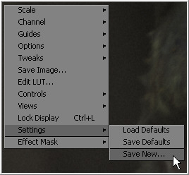
Saving View Settings
Once a view is set up as required, select Setting -> Save New from the view's context menu to create a new setting. Enter a name for the settings and the overall configuration of the view will be stored in the preferences file.
Loading View Settings
To load previously saved settings, select the settings by name from the Setting menu in the view's context menu.
Loading And Saving Defaults For A View
The view can also be returned to its defaults using the Load Defaults option in the Settings portion of the view context menu.
To save a new set of defaults for the view, select the Save Defaults option.
Status Bar Information
General Display Options
Display Options Sub Context Menu
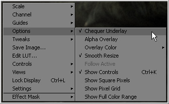
The Display Options Sub Context Menu contains several options to display the views. All of the options listed here can be found in the context menu. Several of them have a button in the view toolbar as well.
- Locking The Display
- Default: Off
- A display can be prevented from updating when it is locked. The display will not update the image from the viewed tool until the view is unlocked. The tool still processes and the new image is queued for display in the view. Toggle this option using the Ctrl-L keyboard shortcut, or by clicking on the Lock button in the view toolbar when viewing a 2D image.
- Alpha Overlay
- Default: Off
- When this option is enabled, the view will show the Alpha channel overlaid on top of the color channels.
- Overlay Color
- Default: White
- Change the color used for the alpha Overlay from the default white using the options in this menu.
- Checker Underlay
- Default: On
- The Checker Underlay shows a checkerboard beneath transparent pixels instead of black. This is the default option for 2D views. Toggle this option by clicking on the Checker button in the 2D view toolbar.
- Smooth Resize
- Default: On
- The Smooth Resize option causes the display view to use a smoother interpolated resizing method when zooming into an image in the views. When smooth resize is disabled, scaling uses the faster nearest neighbor method. This option is enabled by default and can also be toggled by clicking on the SmR button in the view toolbar.
- Follow Active
- Default: Off
- Enabling the Follow Active option will cause the view to always display the currently active tool in the flow.
- Show Controls
- Default: On
- The Show Controls option shows or hides onscreen tool controls in the view. This option is handy when the controls are not necessary or are getting in the way of evaluating the image. This option is toggled using the Ctrl-K keyboard shortcut or by clicking on the Show Controls button in the view toolbar.
- Show Square Pixels
- Default: Off
- Depending on the frame format preferences and the type of footage loaded, many images may have pixels that are rectangular instead of square. Both the NTSC and PAL video standards, as well as some film formats, use rectangular pixels. A computer monitor uses perfectly square pixels.
- Fusion will automatically perform aspect correction when viewing non-square images so that the image seen in the views does not appear squashed or stretched. Although this aspect correction helps to correct the shape of the objects in the image, it can also cause aliasing in the image. Fusion uses a relatively fast resize algorithm to make the correction in the views. This aliasing does not affect the final result. It is an artifact of the display view only. Regardless, its presence can obscure real problems in the image.
- Enabling the Show Square Pixels option will override the aspect correction in the view to confirm that this `tearing' is an artifact of aspect correction and not a problem with the composite.
- Show square pixels can also be toggled on and off using the 1:1 button in the view toolbar.
- For more information on the effect of aspect on the composite and how Fusion handles aspect ratio, see the Frame Formats chapter in this manual.
- Pixel Grid
- Default: Off
- Enabling this option will show a light black grid that outlines the exact boundaries of pixels in the image when the image is scaled in past a certain threshold. Toggle this option with the Grid toolbar button.
- Show Full Color Range
- Default: Off
- Enabling the Show Full Color Range option causes Fusion to automatically normalize any image displayed in the view. Normalization causes the brightest pixel in a color channel to be mapped to a value of 1.0 (white) and the darkest pixel to be mapped to a value of 0.0 (black). Midrange values are scaled appropriately to fit within that range.
- This allows for the visualization of values outside of the normal viewing range, particularly when working with floating point images. It is also useful when viewing Z-buffer or other auxiliary channels, which often use value ranges far different from those in the color channels.
- Toggle this option with the Related View toolbar button.
Display View Label
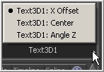
Each display view has a text label at the bottom right of the view toolbar. This Display View Label indicates the name of the tool currently viewed in the display. Clicking on the label will select the viewed tool and, if the tool is not currently visible in the flow area, it will highlight and pan the tool in the flow editor.
Controls List
Click on the small arrow button to the far right of the label for a popup list of the onscreen controls for the selected tools. The currently active control is marked on the menu. Choosing a different control from the menu will activate it for use. This can be handy when several controls are in the exact same position.
If multiple tools are selected, the menu will provide a complete list of all of their onscreen controls. Selecting a control from the list will highlight and activate this control on the view.
Shortcut: Pressing Tab or Shift+Tab will cycle through the onscreen controls, activating each in turn.
See Also: The view's context menu has further options for control management in the Controls submenu.
| The contents of this page are copyright by eyeon Software. |
