Eyeon:Manual/Polylines
From VFXPedia
Contents |
Polylines Introduction
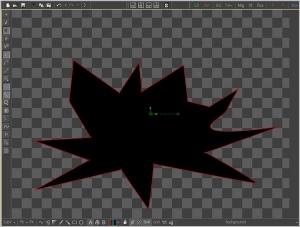
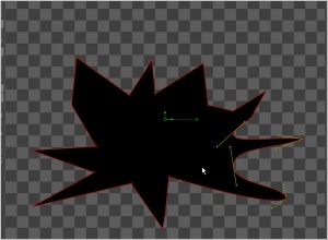
Polylines appear whenever a control is animated with a path or when a tool's effect is masked with a polygon or baseline mask. They also appear in the paint and grid warp tools. In a more basic form, polylines are used to control the animation of every single animation in Fusion, through the spline editor.These simple shapes are used by Fusion for just about everything. As a result, they are extremely flexible, with a considerable amount of controls, modes and options.
This chapter offers an overview of polylines and their operation. It will not discuss how to create paths or effect masks, as these are covered in depth in the Effect Masks chapter and the Motion Paths chapter later in this manual.
Polyline Types
Bezier Polylines
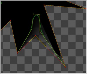
Bezier Polylines are shapes that are composed of key points and Bezier handles. Several points together are used to describe the overall shape of a polyline.Each key point has a pair of Bezier handles associated with it that is used to define the exact shape of the polyline segments passing through each key. Adjusting the angle or length of these Bezier handles will affect whether that segment of the polyline is smooth or linear.
3D software packages, such as Maya, 3ds Max or LightWave, will offer familiarity with many of the basic concepts that relate to the use of Bezier Polylines.
B-Spline Polylines
A B-Spline Polyline is similar to a Bezier spline, however, these polylines excel at smooth shapes. Instead of using a keypoint and two handles for smoothness, the B-spline polyline has just one point, defining a bounding box for the shape. The smoothness of the polyline is determined by the tension of the point, which can be adjusted as needed.
Polyline Toolbars
Whenever a tool that contains one or more polylines is selected, the polyline is shown on all display views and the Polyline Toolbar will appear. The toolbar contains several buttons that make switching polyline modes and options easy to access.To identify each of the buttons, place the mouse pointer over the button until a tooltip that describes the button's function appears. Clicking on a button will affect the currently active polyline (see Polyline Focus below) or the selected polyline points, depending on the button.
To change the size of the toolbar icons, add labels to the buttons or to make other adjustments to the toolbar's appearance, or right-click on the toolbar and select from the options displayed in the toolbar's context menu.
Selecting A Polyline
Keyboard shortcuts and toolbar selections will only affect the currently selected polyline. It is possible to have several polylines in the display view at once so it is important to be able to switch between polylines effectively.In addition to selecting a polyline by clicking on one of its keyframes or segments, use the following methods to make a polyline active.
- TAB And SHIFT-TAB Cycling
- To cycle between available polylines, use the TAB and SHIFT-TAB keyboard shortcuts.
- Context Menu
- Right-click in the view and choose the desired polyline by name from the Controls>Select menu.
- View Toolbar
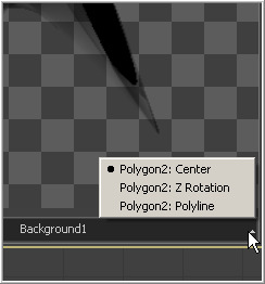
- To the right of the display view toolbar, click on the small arrow icon. This will display a list of all of the controls that are currently displayed in the view. Choosing a polyline from this menu will select the polyline.
Polyline Creation Modes
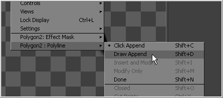
Several different modes are available for creating and modifying polylines. The specific mode used when a polyline is first added will depend on whether the polyline is part of a path or a mask. To change modes, select from the polyline toolbar and use the keyboard shortcut associated with that mode or select the mode from the spline's context menu.
Each of the modes is described in more detail below, together with the keyboard shortcut that is used to set the active polyline into that mode. Take time to explore each of the Polyline Creation Modes offered by Fusion to become comfortable with their operations.
- Click Append (SHIFT-C)
- This mode is the default mode for mask creation. Simply click the mouse pointer in the position where the new point is to be added. Each new point is automatically connected to the last created point. Use Click Append mode to quickly define the rough shape of the mask, then switch to Insert And Modify mode to refine the mask further. It is also useful when the overall shape of a motion path is known but the timing is not yet available.
- To close a polyline created in this mode, place the mouse pointer over the first point created and click when the cursor changes shape. A closed polyline is automatically switched to insert and modify mode. Click append mode is rarely used with paths.
- Insert And Modify (SHIFT-I)
- New points are added to the polyline between existing points on the polyline. Existing points on the polyline are modified by dragging the keys or handles. Points can only be added along the existing polyline.
- Insert And Modify is the default creation mode for motion paths. Any time a control that is animated with a motion path is moved, a new key is created at the current time and added to the end of the polyline, extending or refining the path. Masks, which are created in click append mode, automatically switch to Insert And Modify mode when the mask shape is closed. This makes it easier to add additional points and refine the shape of the mask.
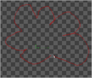
- Draw Append (SHIFT-D)
- The Draw Append mode creates a polyline shape directly on the view, like drawing with a pencil or a paintbrush. Click-drag the left mouse button to draw the desired shape for the path, or use a pen and tablet. This mode is ideal for use in conjunction with a tablet, and for the creation of garbage mattes and effect masks around complex shapes.
Protection Modes
In addition to the modes used to create a polyline, two other modes are used to protect the points from further changes after they have been created.
- Modify Only (SHIFT-M)
- Modify Only allows existing points on the polyline to be modified but new points may not be added to the polyline. Be aware that it is still possible to delete points from a polyline in this mode.
- Done (SHIFT-N)
- The Done mode prohibits the creation of any new points, as well as further modification of any existing points on the polyline.
Closing And Opening Polylines
There are several ways to close a polyline, which will connect the last point to the first. When creating the polyline, place the mouse pointer over the first point created and the pointer will change to indicate that clicking on the points will close the polyline.
Closed polyline masks will normally generate a solid mask, although the mask controls can also be used to create outline shapes. Used more often for masks, closed motion paths are also used to create seamlessly looping motions.
You can also close a polyline using the keyboard shortcut Shift-O, the Close button on the polyline toolbar, or by selecting the Closed option from the polyline's context menu. All of these options are toggles that can also be used to open a closed polygon.
Selecting and Adjusting the Polyline
Polyline Points Selection
To select one or more points on a polyline, click directly on the point or box-select the points by click-dragging a rectangle around them.
To add or remove points from the current selection, hold the Shift or Ctrl keys down while making the selection.
Use CTRL-A to select all of the points on the active polyline.
Moving Polyline Points
The selected polyline points can be moved using either the keyboard or the mouse.
- Using the mouse
- Once the points are selected simply click and drag on the selected points with the mouse. Holding down SHIFT or ALT before click dragging will restrict movement to a single axis.
- Using the cursor keys
- The cursor (arrow) keys on the keyboard can also be used to move selected points. For smaller movements hold down CTRL while using the cursor keys, and for larger movement hold down SHIFT.
- Edit Points
- The E keyboard shortcut will display an edit points dialog that can be used to manually enter positions for one or more selected points. This dialog is described in detail further down the page.
Smoothing a Polyline Segment
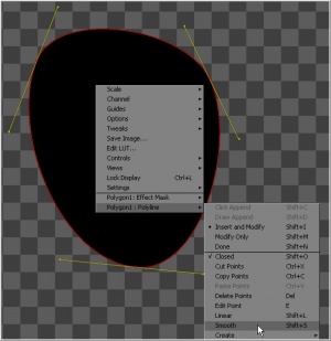
Smoothing a spline segment reveals the Bezier control handles, making it possible to apply shaping to a polyline curve. There are three ways to smooth the selected points on an active polyline.
Use the keyboard shortcut Shift-S while the segment is selected. Use the Smooth button on the polyline toolbar, or select Smooth from the polyline's context menu.
Linearizing a Polyline Segment
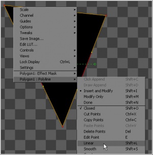
To make certain that a polyline segment is perfectly straight, that segment needs to be linearized. A Linear Segment has no Bezier handles. The segment is always drawn in a straight line between two points on the polyline.There are three ways to make the selected points on an active polyline linear.
Use the keyboard shortcut Shift-L while the segment is selected. Use the Linear button on the polyline's toolbar or select Linear from the polyline's context menu.
Deleting Selected Points
Delete a selected point or group of points by pressing the Delete key, choosing Delete from the context menu or by clicking on the Del button in the toolbar. The shape of the polyline will change to reflect the removal of these points.
Deleting all of the points in a polyline does not necessarily delete the polyline itself. The polyline controls still exist and are simply waiting for points to be created. To delete a polyline, delete the tool or modifier that created the polyline.
Bezier Handles
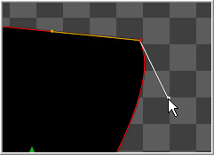
Each control point has two bezier handles that describe tension through the point, helping to determine the shape of the curve. These bezier handles only appear when the point is selected.
Click-drag on a handle to make adjustments to the curve of the segment that emerges from the point. The handle on the opposing side of the point will also move to maintain the relationship between these two handles.
To break the relationship between handles and adjust one handle independently, hold down CTRL while dragging the point. Subsequent changes will maintain the relationship, unless the CTRL key is held during each adjustment.
To constrain the motion of the handle to a single axis, hold ALT down while dragging the handle.
Hold SHIFT down while moving a handle point to adjust the length of both handles without changing the angles.
Edit Points
To display the Edit Points dialog, press E on the keyboard or select Edit Points from the polyline's context menu.
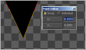
The edit points dialog provides numeric controls for precise control over the position of polyline points in Fusion. When a single point in the polyline is selected, it will bring up a dialog box that contains the X and Y axis values for that point. This dialog box can then be used to edit the location of that point manually by entering the desired value.
It is possible to perform minor mathematical equations in this dialog box. For example, typing 1.0-5 will move the point to 0.5 along the given axis.
When multiple points are selected, all points will be moved to the same position. This is useful for aligning points to the same plane on a specific axis. Changes made to the dialog will affect all selected points. This is useful for lining up several points along a given axis.
In addition to absolute values for the X and Y axis of each point, it is possible to adjust points using an offset from their current position. To change the mode of the Edit points dialog, click once on the label for the axis. The label will change from X to X-Offset or from Y to Y-Offset.
If more than one point is selected, a pair of radio buttons at the top of the dialog box determines whether adjustments are made to all selected points or to just one. If the Individual option is selected, the point to be affected is drawn on the display view surrounded by a larger box. Change which point in the selection is affected using the next and previous buttons that appear at the bottom of the dialog.
Reduce Points
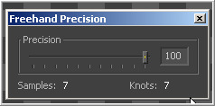
Selecting Reduce Points from the polyline's context menu or toolbar will bring up a dialog box to decrease the number of points used to describe the polyline. Fusion will attempt to maintain the overall shape of the spline while eliminating redundant points from the path. To reduce the amount of points in the path, move the slider to the left.
When the value is 100, no points will be removed from the spline. Use smaller values to eliminate more points. This mode is extremely useful when used in conjunction with the draw points spline creation mode, or to simplify an editable paint stroke.
Advanced Spline Shaping
Transforming Individual Points
Select the points to be transformed and:
- Hold down the T key and click-drag to twist.
- Hold down the S key and click-drag to scale.
- Hold down the X key and click-drag to scale horizontally only.
- Hold down the Y key and click-drag to scale vertically only.
- Hold down the O key and click-drag to offset the points perpendicularly from the polyline.
The position of the mouse pointer when the transformation begins becomes the center used for the transformation.
Shape Box
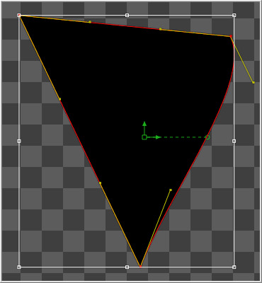
The Shape Box permits free scaling and transformations of the polyline shapes. Toggle the shape box on or off using the Shape Box toolbar button, the Shape Box option in the context menu, or the CTRL-B keyboard shortcut.
If there are selected points on the polyline when the shape box mode is enabled, the shape box is drawn around those points. Otherwise, draw the shape box in the position desired by click-dragging a rectangle.
A four-sided box will be drawn. Select a handle in the middle of a side to resize the polyline along a specific axis, or select a corner handle to shape the polyline along both axis.
Holding down CTRL while dragging a shape box point will apply adjustments from the center of the shape box, constraining the transformation to the existing proportions of the shape box. Holding down SHIFT while dragging a corner handle affects only that handle, allowing skewed and non-uniform transformations.
Other Polyline Options
Stop Rendering
Fusion will attempt to render the tool's result while points are moved on a polyline, providing interactive feedback of the effect the changes will have.
This can be distracting in some situations and can slow down performance on a complex effect. To restrict this behavior so that Fusion only renders when the points stop moving, toggle the Stop Rendering button in the toolbar or select this option from the polyline context menu.
Showing and Hiding Points and Handles
It is often difficult to identify individual points when they are placed closely together. Fusion offers the ability to display both points and their Bezier handles, just points, or handles. Select which display mode is used with the Show Key Points and Show Handles toolbar buttons, or from the polyline's context menu.
Use these options to simplify the screen display when adjusting points placed closely together and to avoid accidentally modifying controls and handles that are adjacent to the intended target.
Importing And Exporting Polylines
Fusion provides methods for importing and exporting polyline shapes in to a common editable ASCII text file or its native format. These methods are used to save a particularly useful or generic mask or path for future use or for use in another application, such as Maya or LightWave.
ASCII Format
To save a polyline to an external ASCII file, right-click on the view and select Export from the context menu. A submenu will appear that contains several options on exactly how the shape will be described in the text file.
- Point
- Selecting Point as an option will cause Fusion to divide the mask into equally spaced points while attempting to preserve the exact shape.
- Bezier
- Select Bezier to cause the output file to contain the precise coordinates of each point in the shape, as well as the position of its associated Bezier handles.
- Key
- Select Key as an option to cause only the position of the existing key points to be exported, ignoring the position of Bezier handles. (It is not possible to select more than one of the above three options. Additionally, the coordinate system to be used by Fusion must be selected when exporting the points.)
- Relative
- The Relative option will describe the X and Y coordinates as offsets that are relative to the center of the mask.
- Absolute
- The Absolute option will describe the coordinates of the points and or handles as values between 0 and 1, using Fusion's native coordinate system.
Once the desired options are selected, choose Export Shape from the context menu and provide a name and path for the output file. To save the timing of a motion path with the file, select Export Path. To import a saved ASCII file, create a polyline and select Import from the polyline's context menu.
A full description of the file format used is available in the appendix of this manual.
Native Format
To save a polyline shape in Fusion's native format, right-click on the header of the mask tool or the path modifier and select Settings>Save As from the context menu. Provide a name and path for the saved file and select OK to write a file with Fusion's *.setting extension. This file will save the shape of a mask or path, and any animation splines applied to its points or controls.
To load the saved setting back into Fusion, create a new polyline of the same type, then select Settings>Load from the mask's context menu.
You can also copy the tool to the clipboard, then paste it into any text editor.
