Eyeon:Manual/Fusion 6/Tool Controls
From VFXPedia
[ Main Manual Page ]
Tool Controls Introduction
Every tool added to a flow in Fusion has a set of parameters, or controls, that determines how that tool behaves. When that tool is selected, the controls for that tool appear in a window on the right side of the screen in the Controls Area. More than one tool can be selected at a time.
Each control window has a header. This is a small title bar for the window that displays the tool's name and a button to collapse or open the window. The control header is also a good place to access the tool's context menu.
Modifiers can also be attached to a tool's controls. Modifiers are tools like expressions, calculations, trackers and paths. When a modifier is connected to a control on a selected tool, its controls will also appear. These controls appear separately in their own modifiers tab for the controls window.
The Controls Area Interface
Maximizing The Control Area
A small button labelled with a pair of arrows can be found at the top of the controls area to the left of the tabs. Click on this button to toggle the Control Area between maximized and regular modes.
In maximized mode, the tool controls are aligned with the top of the window, taking up the maximum available height for the display of controls.
In regular mode, the tool controls are aligned with the bottom of the display views, making the best possible use of horizontal space for the display views.
Viewing The Control Window For A Tool
To open a tool's controls, select the tool from the flow, timeline tree or spline editor tree. If multiple tools are selected, the control windows for all selected tools will appear.
Hiding The Control Window For A Tool
The control window for a tool can be hidden from display so that the controls never appear, even if the tool is selected.
To hide a control window for a tool, right-click on that tool in the flow, or on the control header, and de-select Modes>Show Controls.
To re-enable the display of the control window for a tool, right-click on the tool's tile in the flow and re-select Modes>Show Controls.
Control Area Display Preferences
There are two different ways to display a tool's controls. The default option shows only the control windows for the selected tools. The alternate option shows the controls for all tools in the control window at once.
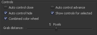
To switch to this mode, select File>Preferences from the menu and open the General Preferences. The following options are available.
When the Auto Control Close option is enabled, the control window for the selected tool is the only open window. Every other control window is automatically closed whenever a new tool is selected.
When the Auto Control Hide option is enabled, the only control window visible is the one for the currently selected tools. All other control windows are hidden to reduce clutter. This is enabled by default. Turn it off to see all tool controls at once.
Selecting A Tool With The Control Header
A tool becomes the active tool when the tool's control header is clicked. Any onscreen controls for that tool will be displayed in the views that contain an image. This is exactly the same as clicking on a tool in the flow to select it. When a tool is the actively selected tool, its control header changes color.
Viewing And Previewing A Tool With The Control Header
To view a tool in one of the display views, click-drag the tool's control header into one of the display views. To make a preview in one of the display views, hold the Alt key while dragging the tool header into the view.
Viewing A Tool's Splines With The Control Header
To view all of the animated parameters associated with a tool, drag and drop the tool into the spline editor. The splines attached to the tool (if any) will automatically be selected and displayed for editing.
Context Menus
Tool Context Menu
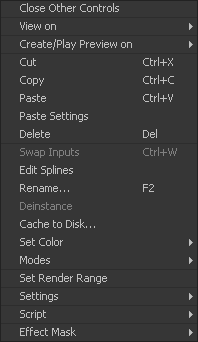
To display the Tool Context Menu from the control window, right-click on the tool header across the top of the controls. This displays the same tool menu options that would be the result of right-clicking on a tool in the flow. See the chapter on the Flow Editor for more information on these options.
Control Context Menu
The context menu for individual controls can also be accessed. For example, right-clicking on a slider will provide the Control Context Menu, with options to animate the control or add additional modifiers. These options are described in more detail through the rest of this chapter.
Common Controls Tab
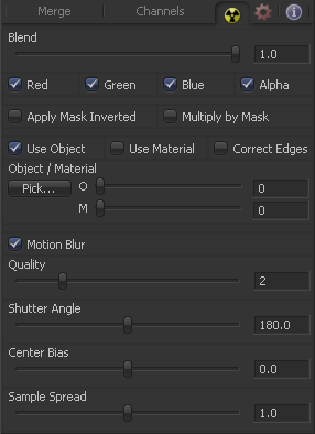
The Common Controls Tab is labeled with a radioactive symbol and can be found on virtually every tool found in Fusion. The common controls are generally found even on third-party plugin tools. This tab collects together controls that would normally have appeared on every tool.
The following controls are generally found in this tab. Some controls may not appear on all tools. For example, motion blur settings have no meaning on a Cineon Log tool.
The Blend control is found in all tools (except loader and creator tools). Use the blend control to blend between the tool's unaltered image input and the tool's final modified output image. When the blend value is 0.0, the outgoing image is identical to the incoming. Normally, this will cause the tool to skip processing entirely, copying the input straight to the output.
The tool is processed even when the input value is zero.
These four checkboxes can be used to limit the effect of the tool to specified color channels. This filter is often applied after the tool has been processed.
For example, if the red checkbox on a transform tool is deselected, the transformation will first be applied to the image, then the red channel from the original input will be copied back over the red channel of the result.
There are some exceptions, such as tools where deselecting these channel selectors causes the tool to skip processing that channel entirely. Tools that do this will generally possess a set of identical checkboxes on another tab in the tool. In this case, the state of the common control channel selector checkboxes are instanced to the channel selectors found elsewhere in the tool.
Masking
Enabling the Apply Mask Inverted option inverts the complete mask channel for the tool. The mask channel is the combined result of all masks applied to a tool.
Selecting this option will cause the RGB values of the masked image to be multiplied by the mask channel's values. This will cause all pixels of the image not included in the mask (i.e. set to 0) to become black.
Object And Material ID Masking
Some 3D software can render to file formats that support additional channels. Notably, the RLA and RPF file formats support object and material ID channels, which can be used as a mask for the effect. This checkbox determines whether the channels will be used if present. The specific material ID or object ID affected is chosen using the next set of controls.
Use these controls to select which ID will be used to create a mask from the object or material channels of an image. Use the Pick button in the same way as the color picker; to grab IDs from the image displayed in the view. The image or sequence must have been rendered from a 3D software package with those channels included.
This checkbox only appears when the Use Object ID or Use Material checkboxes are selected. It toggles the method used to deal with overlapping edges of objects in a multi-object image. When this control is toggled on, the Coverage and Background Color channels are used to separate and improve the effect around the edge of the object. If this option is toggled off (or no Coverage or Background Color channels are available), aliasing may occur on the edge of the mask.
For more information on the Coverage and Background Color channels, consult the Auxiliary Channels chapter.
Motion Blur
This toggles the rendering of Motion Blur on the tool. When this control is toggled on, the tool's predicted motion is used to produce the motion blur caused by the virtual camera's shutter. When the control is toggled off, no motion blur is created.
Quality determines the number of samples used to create the blur. A quality setting of 2 will cause Fusion to create two samples to either side of an object's actual motion. Larger values produce smoother results but increase the render time.
Shutter Angle controls the angle of the virtual shutter used to produce the motion blur effect. Larger angles create more blur but increase the render times. A value of 360 is the equivalent of having the shutter open for one whole frame exposure. Higher values are possible and can be used to create interesting effects.
Center Bias modifies the position of the center of the motion blur. This allows for the creation of motion trail effects.
Adjusting this control modifies the weighting given to each sample. This affects the brightness of the samples.
Comment Tab
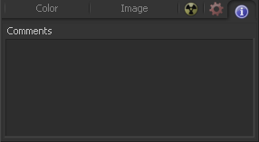
The Comment Tab is marked by a small blue icon that contains the letter I in white. This tab is found on every tool. It contains a single text control that is used to add comments and notes to the tool. Click in the entry area and type the text.
When a note is added to a tool, a small blue icon with the letter I appears on the control header. To see the note in the flow, hold the cursor over the tool tile for a moment. The contents of the comments tab can be animated over time, if required.
Additional controls appear under this tab if the tool is a Loader. See the Creator Tools chapter for details.
Scripting Tab
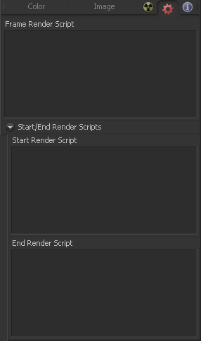
The Scripting Tab is present on every tool in Fusion. It contains several edit boxes used to add scripts that process when the tool is rendering. For more details on the contents of this tab, please consult the scripting documentation.
Scaling and Panning the Control Window
Resizing The Control Window
To increase the overall width of the Control Window, click-drag on the vertical splitter that separates the controls from the work area and displays. Most controls will resize together with the window. This allows for greater precision with sliders, angles and other tools.
The controls have a minimum width of approximately 280 pixels. They will begin to be cropped rather than be resized past this point.
Panning the Control Window
The control window can be panned up or down to reveal portions which have scrolled out of the visible portion of the screen. To pan, either click drag on the scrollbar that appears to the right of the control window, or hold down the middle mouse button and drag while the mouse pointer is positioned over the control window.
Control Animation
Virtually any control found in Fusion can be animated over time. Controls default to static, with no animation. Animate a control by attaching it to an animation curve. Multiple controls can all be connected to the same animation curve.
Animation Curves
When animating a control, the control is connected to an Animation Curve. These curves are made up of splines from one of four spline types. By default, Fusion uses a Bezier spline when a control is animated. This is the type of spline found in most software packages. Change the default spline type from Bezier to one of the other types by changing the Default Animate option in the Globals>Defaults panel of the preferences.
- Bezier Spline
- The shape of a Bezier Spline is determined by keyframes that represent the value of a control at a frame. The values between keyframes are determined by interpolation. With a smooth the curve, the weighting of the interpolation between values is determined by two handles attached to each keyframe.
- Natural Cubic Spline
- A Cubic Spline also uses keyframes to represent the value of the control in time, and appears identical to a Bezier curve when the interpolation between points is linear. When the interpolation is smooth, a cubic spline uses a different method of calculating interpolation that eliminates the need for handles.
- NURB Spline
- NURB splines also use keyframes, but the value of the keyframe only directly maps to the value of the control when the spline is linear. When the spline is smooth, the keyframes define the shape of the curve with no direct relationship to the value. Although it can be used to create very naturalistic motions, this spline type is rarely used because it is so difficult to control.
- Also see the Spline Editor chapter of this manual.
To Animate A Control Using The Default Animation Curve
Right-click on the control and select Animate from the context menu. This will attach the control to an animation curve and set a keyframe for the current value at the current frame.
To Animate A Control Using A Non-Default Animation Curve
Right-click on the control and select the desired curve type from the context menu's Modify With submenu.
To Set A Keyframe On An Animated Control
Keyframes are automatically updated whenever the value of a control attached to an animation curve is changed. If there is a keyframe already at the current time, the keyframe is updated, otherwise, a new keyframe is created.
To set a new keyframe without changing the value of the control, right-click on the control and select Set Key On Tool Name: Spline Name from the context menu. This is handy when the animation is to hold a specific value for a length of several frames.
Removing Animation
To remove an animation spline from a control, right-click on the control and select Remove Bezier Spline or Remove Cubic Spline from the context menu.
Connecting A Control To An Existing Animation Curve
Right-click on the control and select the name of the animated control to be connected to from the context menu's Connect To submenu.
Connecting One Control To Another Without Animating Them
It is often useful to connect two controls together without either control having to be animated. In this case, one control must be published first. This is done by right-clicking on the control and selecting Publish, then connecting the second control as described above.
For example, to connect a control to a Shake modifier, place the pointer over the control. Press the right mouse button and select Modify With from the context menu that appears. Then select the modifier that is to act on that control. The context menu will list only modifiers that are valid for that control.
For more information on connections and modifiers, see the Connections And Modifiers chapter later in this manual.
| The contents of this page are copyright by eyeon Software. |

