Eyeon:Manual/Fusion 6/pCommonControls
From VFXPedia
[ Main Manual Page ]
Particle Common Controls [pCC] | |
|
The Common Controls can be found in every Particle tool inside Fusion. | |
Contents |
Conditions Tab
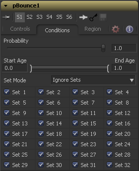
This control determines the Probability or percentage chance that the tool will affect any given particle.
The default value of 1.0 will affect all particles. A setting of 0.6 would mean that each particle has a 60 percent chance of being affected by the control.
Probability is calculated for each particle on each frame. For example, a particle that is not affected by a force on one frame has the same chance of being affected on the next frame.
This range control can be used to restrict the effect of the tool to a specified percentage of the particle lifespan.
For example, to restrict the affect of a tool to the last 20 percent of a particle's life, set the start value to 0.8 and the end value remains at 1.0. The tool on frames 80 through 100 only affect a particle with a lifespan of 100 frames.
This menu control determines if the particle tool's effect will be applied to all particles, limited only to particles from a specified set(s), or applied to all particles except the selected set(s).
Sets are assigned by the tools that create particles the pEmitter, pImage Emitter, the pChangeStyle and the pSpawn tools.
Regions Tab
Regions are used to restrict the tool's effect to a geometric region or plane, and to determine the area where particles are created in a pEmitter tool. There are seven types of regions, each with its own controls.
In 2D, the Particles will be created anywhere within the boundaries of the image. In 3D, this region describes a cube 1.0 x 1.0 x 1.0 units in size.
Bezier mode uses a user-created polyline to determine the region where particles are created. The Bezier mode works in both 2D and 3D modes, however the Bezier polyline region can only be created in 2D.
To animate the shape of the polyline over time or to connect this polyline to another polyline, right-click on the Polyline label at the bottom of the control and select the appropriate option from the context menu.
A Bitmap source from one of the other tools in the composition will be used as the region where particles are born.
A full 3D Cube is used to determine the region within which particles are created. The height, width, depth and XYZ positions can all be determined by the user and animated over time.
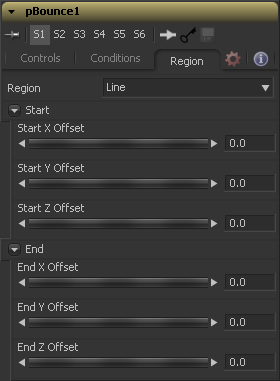
A simple Line control determines where particles are created. The Line is composed of two end-points, which can be connected to Paths or Trackers, as necessary. As with Bezier, this region type works in 3D but the line itself can only be created and adjusted in 2D.
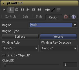
Any 3D Mesh can be used as a region since Fusion 6.1. In Mesh mode the region can also be restricted by the Object ID using the ObjectID slider. See below for a deeper explanation of how mesh regions work.
The Rectangle region type is like the Cube type, except that this region has no depth in Z space. Unlike other 2D emitter regions, this region can be positioned and rotated in Z space.
This is a spherical 3D emitter region with size and center Z controls. Sphere (3D) is the default region type for a new pEmitter tool.
(Line mode only) These controls define the Start and End point of the line in 3D Space.
Mesh Regions
The Region Type control allows the artist to choose whether the region will include the inner volume, or just the surface. For example, when a mesh region is used with a pEmitter, this control would determine whether the particles are emitted from the surface or the full volume.
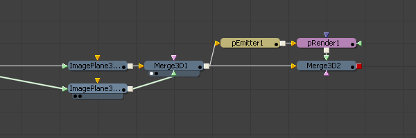
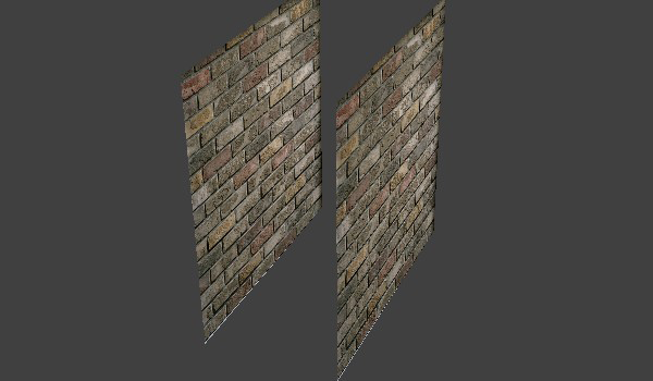
The Winding Rule and Winding Ray Direction controls determine how the mesh region will handle particle creation with meshes which are not completely closed, as is common in many meshes imported from external applications. This scenario is common with imported mesh geometry, and even geometry which appears closed will frequently appear to 'leak' thanks to improperly welded vertices. To determine if a particle is in the "interior" of an object a ray is cast from infinity through that particle and then out to -infinity. The Winding Ray Direction determines which direction this ray is cast in. Each time a surface is pierced by the ray it is recorded and added onto a total to generate a winding number. Going against a surfaces "normal" counts as +1 and going with the normal counts as "-1". The Winding Rule is then used determine what is inside/outside. For example, setting the Winding Rule to "Odd" means that only particles with odd values for the winding number are kept when creating the particles. The exact same approach is used to ensure that polylines which intersect themselves are closed properly. For example, the following flow and image shows two image planes being used as a mesh region for particle creation.
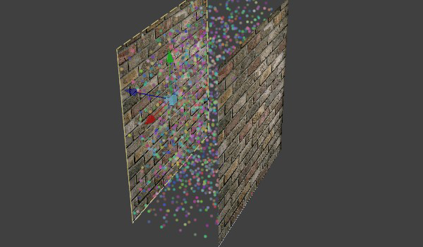
By setting the regions Winding Ray Direction to the Z (blue) axis this mesh can then be treated as a closed volume for purposes of particle creation, as pictured below.
Selecting this check-box allows the artist to use the slider found below the check-box to filter the scene geometry so that only geometry with a matching ObjectID property is used as part of the region. This menu control determines if the particle tool's effect will be applied to all particles, limited only to particles from a specified set(s), or applied to all particles except the selected set(s).
Sets are assigned by the tools that actually create particles. These are the pEmitter, pImage Emitter, the pChangeStyle and the pSpawn tools.
Tips for pCommonControls (edit)
EyeonTips:Manual/Fusion 6/pCommonControls
| The contents of this page are copyright by eyeon Software. |
