Eyeon:Manual/Tracking
From VFXPedia
Contents |
Tracking Overview
Tracking is one of the most powerful automation tools available to a compositor. A tracker can follow a pattern of pixels in an image over time, generating a motion path from the pattern's movement. This information is then used to perform a variety of tasks, including matchmoving, image stabilization, sign replacement and driving the positions of points on a mask.
Detailed reference for each of the controls found in the tracker can be found in the Tracker section of the tool reference. This chapter is intended to provide a more general description on how to use a tracker.
The basic approach to tracking has two steps. A pattern is selected and tracked and the results are applied to one of several operations using the data. The structure of the tool controls reflects this; select the patterns and solve them in the Trackers tab, then switch to the Operations tab to make use of the paths just created.
Tracking Operations
Connecting Controls To A Tracker
The position of a tracker pattern is often used to drive the position of a center or axis control. For example, track the face of a suspect in a surveillance tape and connect the center of a mask on a blur tool to the result. This will obscure the features for broadcast.
Stabilizing
One or more trackers can be used in Stabilizing an image, removing all of the motion from the sequence or smoothing out vibration and shakiness. A single tracker pattern is used to stabilize position only. Multiple patterns can be used together to stabilize rotation and scaling.
Match Moving
The reverse of stabilizing is Match Moving, which detects position, rotation and scaling in an image sequence using one or more patterns. Instead of removing that motion, it is applied to another image that matches the movement so that the two images can be composited together.
Corner Positioning
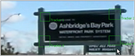
Corner Positioning tracks four patterns. The result is used to map the four corners of a new image into the image. This technique is generally used for sign replacement.
Perspective Positioning
Perspective Positioning tracks four patterns in an image sequence. The four patterns describe the four corners of a rectangle. Each corner is then mapped to a corner of the image, rescaling and warping the image to remove all apparent perspective.
Pattern Overview
What Is A Pattern?
A Pattern is the region of pixels that are selected for tracking in an image. The pattern is represented in the display views as a solid rectangle when the tracker tool is active. A single tracker tool can have many patterns defined. Each pattern will produce its own path.
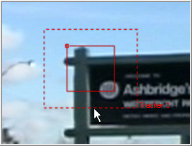
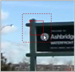
Start with one pattern already set up when first adding the tracker tool. This pattern shows as a small rectangle in the view. When the pointer is placed over the pattern rectangle, the control expands and two rectangles appear. The outer has a dashed line and the inner has a solid line. The outer rectangle is the search area and the inner rectangle is the pattern.
Move the pattern by clicking on the small box in the top left of the pattern rectangle. Drag it over the pixels to track. The pattern rectangle is resizable. Adjust the pattern size by click-dragging on the edges of the rectangle.
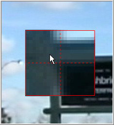
While dragging the pattern rectangle, an overlay pop-up will appear. The overlay shows a zoomed version of the pixels contained within the rectangle to assist with precise positioning of the pattern.
Pattern Search Areas
When the mouse pointer is over the on-screen control for a pattern, a second rectangle with a dotted border will appear surrounding the pattern. This outer rectangle represents the search area.When processing the pattern for tracking, Fusion will search the region surrounding the last known tracker position in an attempt to re-locate the pattern. The larger the search area, the longer it will take Fusion to track.
For example, tracking a pattern that is moving quickly across the screen from left to right requires a wide search area but does not require a very tall one, since all movement is horizontal. If the search area is smaller than the movement of the pattern from one frame to the next, the tracker will likely fail and start tracking the wrong pixels. It is important to take the speed of the motion into consideration when setting the search area.
- Note
- The size of the search area can be animated over time. This is useful for times when the track pattern accelerates or decelerates rapidly part of the way through the scene.
Adding New Patterns
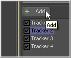
Each tracking tool is capable of tracking multiple patterns. The tracker tool starts with only a single pattern. Additional patterns can be added by clicking on the Add button immediately above the Tracker List control.
Multiple patterns are useful when stabilizing and corner or perspective positioning. They also help to keep the flow from becoming cluttered by collecting into a single tool what would otherwise require several tools.
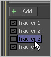
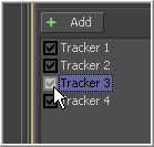
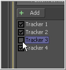
Beside the name for each pattern in the tracker list is a checkbox that can be used to set the pattern into one of three states.
- Enabled (Black Checkbox)
- An Enabled tracker will re-track its pattern every time the track is initiated. Its path data is available for use by other tools and the data is available for stabilization and corner positioning.
- Suspended (Grey Checkbox)
- A Suspended tracker does not re-track its pattern when the track is initiated. The data is locked to prevent additional changes. The data from the path is still available for other tools. The data is also available for advanced tracking modes like stabilization and corner positioning.
- Disabled (Clear)
- A Disabled tracker does not create a path when tracking is initialized. Its data is not available to other tools or for advanced tracking operations like stabilization and corner positioning.
Pattern Selection
Fusion's tracker works by searching each frame for the pixels contained in the pattern. In order for a track to be successful, a fairly high contrast and unique region of the image must be located in the footage. This process is known as Pattern Selection.
The first step in pattern selection is to review the footage to be tracked several times. Watch for candidate patterns that are visible through the entire range of frames, where the contrast is high and the shape of the pattern does not change over time. The more unique the pattern, the more likely the track is to be successful.
Often, no single candidate point will fulfill all of the above requirements. Select the best possible ones. Have another look at the footage and watch the selected patterns to identify the frames where the pattern moves the most. Identifying the maximum range of a pattern's motion will help to determine the correct size for the pattern search area.
It is not uncommon to have a scene that requires the use of several different patterns to generate a single path. This most often occurs because the pattern moves out of frame or is obscured by another scene element for a period of time. Combining patterns into a single pattern is described later in the chapter.
Selecting an Image Channel
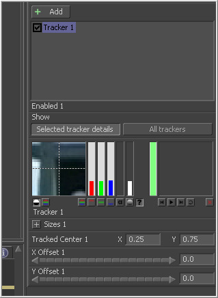
When a pattern of pixels is selected, Fusion automatically selects the color channel used for tracking the pattern based on an analysis of each channel for contrast, clarity and reliability. The channels selected are highlighted in the bars to the right of the pattern display window in the tool controls.
To override this automatic channel selection, select the buttons beneath the bars for each channel to determine the channel used for tracking.
Fusion is capable of using any one of the color channels, the luminance channels or the alpha channel to track a pattern. Tracking a single channel is usually faster than tracking all channels or luminance.
Try to choose the cleanest, highest contrast channel for use in the track. Channels that contain large amounts of grain should be avoided. Bright objects against dark backgrounds often track best using the luminance channel.
Selecting Patterns For Stabilization
When using the trackers to stabilize an image, the location of the pattern when it was selected is used to determine precisely how the image will be stabilized.
Select as many patterns as possible; at least two are required to correct for rotation. Scaling three patterns is better, and more will usually improve the quality of the solution. Try not to select just any potentially valid pattern in the sequence, as some patterns will make the solution worse rather than better.
The following guidelines will help when selecting patterns for stabilization.
- Locate patterns at the same relative depth in the image. Objects further in the background will move in greater amounts compared to objects in the foreground due to perspective distortion. This confuses the stabilization calculations, which do not compensate for depth.
- Locate patterns that are fixed in position relative to each other. Patterns should not be capable of moving with reference to each other. The four corners of a sign would be excellent candidates, while the faces of two different people in the scene would be extremely poor choices for patterns.
See the section on stabilization later in this chapter for more about stabilization and pattern selection for stabilization.
Tracking The Pattern
Once the patterns are selected, Fusion can be set to track the patterns and create paths that represent their position for each frame. Each pattern will produce its own path.
Before initiating the track, set a render range. This is usually a range of frames during which the pattern is visible in the frame or the entire range of the clip.
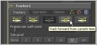
Once the render range is set, click on any of the Tracking Transport buttons in the tracking tool's controls to initiate tracking. Clicking on any of these buttons will cause Fusion to enter rendering mode and work with the flow cannot be done interactively until rendering is complete.
The five buttons in this array are to track backward from the start of the render range, backward from the current frame, stop tracking, track forward from the current frame, and track forward from the start of the render range (in that order).
Halt a render at anytime by clicking on the Stop Tracking button in the tracker transports, by clicking Stop Render at the bottom of the screen or by pressing the Escape key. Pattern tracking will stop automatically when it reaches the end of the render range (or the start when tracking backward).
If the tracker is selected and it is being viewed in a display view, the progress of the tracker as it progresses is visible. If a problem arises with any of the patterns, stop the render and re-evaluate the pattern or select a new pattern and try again. Turning on one of the adaptive modes (described below) or changing the image channel used to track that pattern often helps.
When tracking is complete, the path will be connected to the pattern. The path from that pattern can now be connected to another tool or used for more advanced operations like stabilization and corner positioning.
Confirming the track with the pattern flipbooks
Each pattern has a pair of thumbnail windows shown in the tracker's control window. The left window shows the pattern that is selected.
The small window to its right is interesting because it is updated during the track to show the actual pattern acquired on each frame. Each pattern adds these images to a Flipbook and, once the render is complete, play back this thumbnail pattern flipbook to evaluate the accuracy of the tracked path.
In previous versions of Fusion, the flipbook was only built for pattern windows that were visible (i.e. when All Trackers mode was selected). Fusion now builds trackers for all patterns, regardless of whether they are visible or not.
Adaptive Tracking
Even the most ideal pattern will usually undergo shifts in profile, lighting conditions and other variables. These can adversely affect pattern recognition to the point that a pattern becomes unusable.
The tracker offers three modes of pattern acquisition during tracking that can help to correct these conditions. The modes can be set using the Adaptive Mode button array in the tracker's tool controls.
The adaptive mode is applied to all active patterns while tracking. If only some patterns with a specific adaptive mode are to be tracked, disable all other patterns in the list before proceeding.
- None
- This pattern within the rectangle is acquired when the pattern is selected, and that becomes the only pattern used during the track.
- Every Frame
- Adaptive tracking starts using the pattern selected, then re-acquires the pattern at each frame. The pattern found at frame 1 is used in the search on frame 2, the pattern found on frame 2 is used to search frame 3, and so on. This method helps the tracker adapt to changing conditions in the pattern.
- Imagine tracking a hand that is closing into a fist, for example. Every Frame tracking is slower and can be prone to drifting from subpixel shifts in the pattern from frame to frame. Its use is therefore not recommended unless other methods fail.
- Best Match Tracking
- Best Match Tracking works in much the same way as adaptive tracking, however, it will not re-acquire the pattern if the difference between the original pattern and the new one is too great. This helps to prevent cases where transient changes in the image cause the tracker to become confused.
If a shadow passes over the tracker point, the every frame tracking mode may start tracking the shadow instead of the desired pattern. The best match mode would detect that the change from the previous frames' pattern was too extreme and would not grab a new pattern from that frame.
Obscured Patterns
Often, there is an otherwise ideal pattern that is obscured or blocked from tracking for a portion of the sequence (for example, when tracking a light that passes behind a pillar).
In these situations, avoid tracking in the frames where the pattern is obscured. This can be accomplished by setting the render range to stop immediately before the frame with the obscured pattern and tracking to that frame. Set the render range to the frame immediately after the pattern becomes visible again and re-select the pattern with the onscreen controls. Begin tracking again. The tracker will append to the existing path, automatically interpolating between the existing keyframes.
Additional points may be inserted in the non-tracked path to compensate for any non-linear motion in the tracked pattern.
The tracker path may first need to be set to Insert And Modify mode so that new points can be added.
Change Current Time to each frame in the missing region and reposition the Track Center control to match the expected position of the tracker.
Patterns That Leave The Frame
There are two options when a tracker leaves the frame. If the pattern re-enters the frame, treat it like an obscured pattern (above). If the pattern does not re-enter the frame, or it is undesirable to hand track portions of the movement, use the Track Center (Append) mode to select a new pattern.
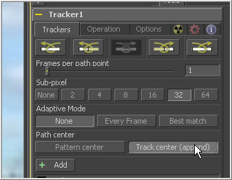
The track center (append) mode selects a new pattern that will continue to add keyframes to the existing path. The offset between the old pattern and the new pattern is automatically calculated.
When the pattern has left the frame, or has become untrackable for some reason, change the current time to the last frame that tracked successfully and click the Track Center (Append) button in the tracker's tool controls. Reposition the pattern selector to the new pattern and restart tracking from the current frame.
When selecting a pattern to use in appending to an existing path, a pattern that is close to the old pattern and at the same apparent depth in the frame generates the best results. The further away the new pattern is, the more likely it is that perspective and axial rotation will disturb the accuracy of the tracked result.
When tracking to stabilize an image using multiple points, it is not necessary that all patterns in the tracker exist for all frames in the sequence. Patterns that are blended out of the solution can fade out as they become invalid. New patterns are blended into the solution as they become available to avoid radical shifts in the tracker average used for stabilization. See the section on Stabilization below for details.
Tracker Offsets
Often, the pattern selected for tracking is not exactly the same as the pattern required for the track. For example, the pattern to be tracked is a button on an actor's sleeve but the effect requires the person's hand to be glowing. To cause the glow's effect mask to be centered on the actor's hand, it would be necessary to make use of the Tracker Offset control.
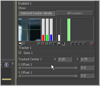
The tracker offset allows for constant or animated positional offsets to be created relative to the actual tracker's pattern center. Position an offset from the pattern's tracked position using the X Offset and Y Offset controls in the tracker's pattern controls.
The position of the offset in the display view will be shown by a dashed line running from the pattern center to the offset position. This control cannot be adjusted within the display view. The offset must be set with the tool controls.
Once an offset for a pattern is set, connect other positional controls to the tracker's offset menu using the Connect To>Tracker: Offset Position option in the control's context menu. The path created during the track remains fixed to the center of the pattern.
The tracker tool displays a toolbar in the display views with a single button. Selecting this button will allow the offset for each pattern to be visible and manipulated as an onscreen control in the views.
Match Moving and Stabilizing
There are several ways to stabilize footage with Fusion, and an almost dizzying array of options. Fusion is capable of stabilizing footage to completely remove motion from the scene or smooth existing motion. Fusion can also apply the motion from one plate to another, basically matching the movement and stabilizing one shot with reference to another. Here are some common scenarios for stabilization that are handled in Fusion's tracker.
- A sequence that should be steady has vibrations or undesirable movement.
- A sequence that requires a smooth camera move suffers from jarring.
- A static CG element must be believably added to a moving sequence.
- Two sequences with different motions must be composited together.
Stabilizing Motion
Stabilizing Motion completely removes the appearance of motion from the image. The motion from frame to frame is calculated, and the contents of the frame are transformed to return the image to a reference position. This position can be either the start or end of the sequence or a manually-selected frame from the sequence.
Stabilization can correct for position with as little as one pattern. Two or more patterns are required to correct for rotation or scaling within the image. See Selecting Patterns For Stabilization above for more details on selecting useful patterns for stabilization.
When the Match Moving button is selected in the tracker's Operations tab, the tracker can use the data from its patterns for stabilization. Only the controls that are applicable for stabilization operations will appear in the operations tab.
Several of the stabilization controls are always available, collected under the Stabilize Settings Reveal button. These controls are available at all times because the steady and unsteady positions of a tracker are always published. This makes them available for connection by other controls, even when the tracker's operation is not set to match moving.
- Merge
- The Merge button array determines to what input the stabilization data is applied. When stabilizing an image to remove all motion, or smooth the motion, the merge button should be set to BG Only. When tracking to remove all motion from a sequence, set the merge mode to BG Only, the reference control to Start, End or Select Time, and the Axis to Tracker Average or Selected Tracker.
- Position/Rotation/Scaling
- Use the Position, Rotation and Scaling checkboxes to select what aspects of the motion are corrected.
- Reference
- The Reference controls establish whether the image is stabilized to the first frame in the sequence, the last frame or to a manually-selected frame. Any deviation from this reference by the tracked patterns is transformed back to this ideal frame.
- Axis
- The Axis for the stabilization is used to calculate the center of rotation and scaling calculations. This is usually the average of the combined pattern centers but may be changed to the position of a single tracker or a manually-selected position.
- Edges
- The Edges button array determines whether the edges of an image that leave the visible frame are cropped, duplicated or wrapped when the stabilization is applied. Wrapping edges is often desirable for some methods of match moving, although rarely when stabilizing the image for any other purpose. These controls are described in greater detail in the tool references for the tracker later in this manual.
Smoothing Motion
When confronted with an image sequence with erratic or jerky camera motion, the overall motion will need to be preserved without losing the essence of the original camera motion.
The start and end reference option is designed for this technique. Instead of stabilizing to a reference frame, the tracked path is simplified. The position of each pattern is evaluated from the start of the path and the end of the path. Intervening points are ignored entirely and smooth, linear motion replaces the existing motion.
To preserve some of the curvature of the original motion, increase the value of the Reference Intermediate Points slider that appears when the Start and End Reference mode is selected.
When tracking to existing smooth camera motion, ensure that the Start and End reference mode is enabled and set the Merge mode to BG Only. It is recommended to leave the axis control set to Tracker Average.
MatchMoving
Footage may need to be stabilized so that an element from another source can be added to the shot. After the element or effect has been applied, the stabilization should be removed to make the shot look natural again.
Match moving essentially applies the movement from the tracked sequence to another.
There are two ways to perform match moving. One method involves connecting to other tools, such as transform or merge, to a tracker's outputs. This method is described in greater detail below.
The other method is to stabilize an image by trying to remove all motion, as described above. Instead of setting the Merge button array to BG Only, set it to FG over BG, FG Only, or in rare occasions BG over FG.
When using this method, provide a foreground image to the tracker using the second (green) input on the tracker tool's tile.
When the FG over BG or BG over FG is enabled, additional controls will appear for merge options. These controls are fully documented in the documentation for the Merge tool in the tool references, and they are not described further here.
Enabling the FG only mode will apply the motion from the background to the foreground, and the tracker will only output the modified FG image. This result can later be merged over the original, allowing further modifications of the foreground to be applied by standard Fusion tools before merging the result over the background plate.
Corner Positioning
The Corner Positioning Operation maps the four corners of a foreground image to four patterns within the tracker. This operation or technique is most commonly used for sign replacements.
The corner positioning operation of the tracker requires the presence of a minimum of four patterns. If this operation mode is selected and there are not four patterns set up in the tracker already, additional patterns will automatically be added to bring the total up to four.
When this operation mode is active, a set of drop-down boxes will appear to select which tracker relates to each corner of the rectangle. This operation has no affect when the merge control buttons are set to BG only.
Tracker Outputs
One of the most common applications for a tracked pattern is using the tracked position or path to drive the position of another tool's control. For example, track an eye and color correct the eye to blue using an effect mask. Then select and track the eye, create a color corrector with the desired settings and create a mask in the shape of the eye. Connect the center of the mask to the tracker's position.
In addition to the path, each pattern outputs five values for use as connections to other control's possible connections that are available for use by other tools.
To connect a position control to a tracker, select the connection type from the controls context menu (for example, Transform 1: Center>Connect To> Tracker 1: Position).
The connection types available are are follows.
- Offset Position
- Offset Position refers to the position of the tracked pattern's center in the image. If an offset has been set for three tracker positions, the offset is also taken into account.
- Steady Position
- Steady Position refers to the position of the tracker on the frame the pattern was selected. This connection will output the inverse of the tracked pattern's motion. Use this connection to steady the tracked image according to the pattern's movement.
- Unsteady Position
- Unsteady Position refers to the opposite position of the tracker relative to the tracker's steady position. Connect to this option to re-introduce the original movement on an image after an effect or new layer has been added.
- Steady Size
- The Steady Size connection outputs the inverse of the tracked pattern's scale.
- Steady Angle
- The Steady Angle connection outputs the inverse of the tracked pattern's angle. This task is commonly referred to as Match Move and can be accomplished in Fusion using either the Stabilizer tool, or the Steady and Unsteady positions of the tracker.
The connections above are output by each individual pattern. The tracker tool itself also outputs a steady position, angle and size output. The values of these outputs are calculated using all of the patterns in that tracker, as configured by the Stabilize Settings controls in the tracker's operations tab.
To use the connections to perform a match move, connect a Transform Center (not a merge or a DVE) to the tracker's Steady Position, as described in stabilizing footage with a tracker in this chapter. Set the transform tools mode to Wrap Edges so that pixels will not get cropped from the image when it is stabilized. Add a second static layer to the stabilized footage.
Add another transform tool to the flow after the merge and connect the new Transform Center to the tracker's Unsteady Position. Make certain that this transform is also set to Wrap Edges. The image will be restored to its original state with the additional effect included.
To better understand how this works, imagine a pattern that is selected at frame 1, at position 0.5, 0.5. The pattern does not move on frame 2 so its position is still 0.5, 0.5. On the third frame, it moves 10 percent of the image's width to the right. Now its position is 0.6, 0.5.
If a transform center is connected to the steady position output of the tracker, the transform tool's center is 0.5, 0.5 on the first and second frames because there has been no change. On frame 3, the center moves to 0.4, 0.5. This is the inverse of the horizontal motion that was tracked in the pattern, moving the image slightly to the right by 10 percent of the image width to counteract the movement and return the pattern of pixels back to where they were found.
Tracker Modifier
Another technique for adding a tracker directly to a control is to apply the tracker as a modifier. To re-use an example from earlier in this chapter, imagine that you needed to track an actor's eyes so that an unearthly, alien glow could be applied to the eyes. Add a glow tool and then create an ellipse mask in the shape of the eye.
Right-click on the center of the mask and select Ellipse x Center>Modify With>Tracker Position>Steady Position or Unsteady Position. This would add a modifier with a set of controls almost identical to those found in the tracker tool itself.
The differences between a Tracker Modifier and a tracker tool are as follows.
- The tracker modifier can only track a single pattern.
- A source image must be set for the tracker modifier.
- The tracker modifier can only output a single value and cannot be used for complex stabilization procedures.
The default source image for the modifier is the tool immediately upstream of the tool that contains the modifier (i.e. when adding a tracker modifier to a glow tool with a loader as its input, the tracker source input will default to the output of the loader).
Set a different source image for the tracker modifier by typing in the name of the tool. Alternately, drag and drop the source tool from the flow into the text box control.
