Eyeon:Manual/Fusion 6/Camera 3D
From VFXPedia
[ Main Manual Page ]
The Camera 3D tool generates a virtual camera though which the 3D environment can be viewed. It closely emulates the settings used in both real and virtual cameras in an effort to make matching the cameras used in other scene elements as seamless as possible.
The camera should be added to the scene using a Merge 3D tool. Displaying a camera tool directly in the display views shows only an empty scene - there is nothing for the camera to see. To view the scene through the camera, view the scene from the Merge 3D tool that introduces the camera, or any tool downstream of that Merge 3D. Then right click in the view and select Camera -> Cameraname from the context menu.
Right clicking on the axis label found in the bottom corner will display the Camera sub-menu directly.
The aspect of the display view may be different from the aspect of the camera, so that the view through the camera interactively may not match the true boundaries of the image which will actually be rendered by the Renderer 3D tool. To assist the artist in framing the shot, guides can be enabled that represent the portion of the view the camera actually sees. Right click in the view and select an option from the Guides -> Frame Format sub-menu. The default option will use the format enabled in the Composition -> Frame Format preferences. To toggle the guides on or off select Guides -> Show Guides from the displays context menu, or use the Ctrl + G keyboard shortcut when the view is active.
The Camera 3D tool can also be used to perform Camera Projection, where a 2D image is projected through the camera into 3D space. This can be done as a simple Image Plane aligned with the camera, or as an actual projection, similar to the behavior of the Projector 3D tool, with the added advantage of being aligned exactly with the camera.
The Image Plane, Projection and Materials tabs will not appear until a 2D image is connected to the Camera 3D tool in the Flow Editor.
The Camera Tool has built in stereoscopic features. They offer control over eye separation and convergence distance. The camera for the right eye can be replaced using a separate camera tool connected to the green input.
Additionally the plane of focus control for depth of field rendering is also available here.
External Inputs
The following inputs appear on the tools tile in the Flow Editor.
- Camera3D.SceneInput
- [ gold, required ] This input expects a 3D scene.
- Camera3D.RightStereoCamera
- [ green, optional ] This input should be connected to another Camera 3D tool. It is used to override the internal camera used for the right eye in stereoscopic renders and displays.
- Camera3D.ImageInput
- [ magenta, optional ] This input expects a 2D image. The image is used as a texture when camera projection is enabled, as well as when the camera's Image Plane controls are used to produce parented planar geometry linked to the cameras field of view.
Controls
The options in this tab are used to set the camera's clipping, field of view, focal length and stereoscopic properties.
Use the Projection Type button to choose between Perspective and Orthographic cameras. Generally, real world cameras are perspective cameras. An orthographic camera uses parallel orthographic projection, a technique where the view plane is perpendicular to the viewing direction. This produces a parallel camera output that is undistorted by perspective.
Orthographic cameras only present controls for the near and far clipping planes, and a control to set the viewing volume.
The clipping plane is used to limit what geometry in a scene is rendered based on the objects distance from the camera's focal point. This is useful for ensuring that objects which are extremely close to the camera are not rendered, and for optimizing a render to exclude objects which are too far away to be useful in the final rendering.
The default perspective camera ignores this setting unless the the Adaptively Adjust Near/Far Clip checkbox control below is disabled.
The values are expressed in units, so a far clipping plane of 20 means that any object more than 20 units distant from the camera will be invisible to the camera. A near clipping plane of 0.1 means that any object closer than 0.1 units will also be invisible.
When selected the renderer will automatically adjust the camera's near / far clipping plane to match the extents of the scene. This setting overrides the values of the Near and Far clip range control described above. This option is not available for Orthographic cameras.
The Viewing Volume Size control only appears when the Projection Type is set to Orthographic. It determines the size of the box that makes up the camera's field of view.
The Z distance of an orthographic camera from the objects it sees does not affect the scale of those objects, only the viewing size does.
Use the Angle of View Type button array to choose how the camera's angle of view is measured. Some applications use vertical measurements, some use horizontal and others use diagonal measurements. Changing the Angle of View type will cause the Angle of View control below to recalculate.
Angle Of View defines the area of the scene that can be viewed through the camera. Generally, the human eye can see much more of a scene than a camera, and various lenses record different degrees of the total image. A large value produces a wider angle of view and a smaller value produces a narrower, or more tightly focused, angle of view.
The angle of view and focal length controls are directly related. Smaller focal lengths produce a wider angle of view, so changing one control automatically changes the other to match.
In the real world, a lens' Focal Length is the distance from the center of the lens to the film plane. The shorter the focal length, the closer the focal plane is to the back of the lens. The focal length is measured in millimeters. The angle of view and focal length controls are directly related. Smaller focal lengths produce a wider angle of view, so changing one control automatically changes the other to match.
The relationship between focal length and angle of view is: angle = 2 * arctan[aperture / 2 / focal_length]
Use the vertical aperture size to get the vertical angle of view, and the horizontal aperture size to get the horizontal angle of view.
This value is used by the OpenGL Renderer to calculate depth of field. It defines the distance to a virtual target in front of the camera.
Stereo Method
Allows to adjust your stereoscopic method to your preferred working model.
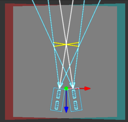
Both cameras point at a single focal point. Though the result is stereoscopic, the vertical parallax introduced by this method can cause discomfort by the audience.
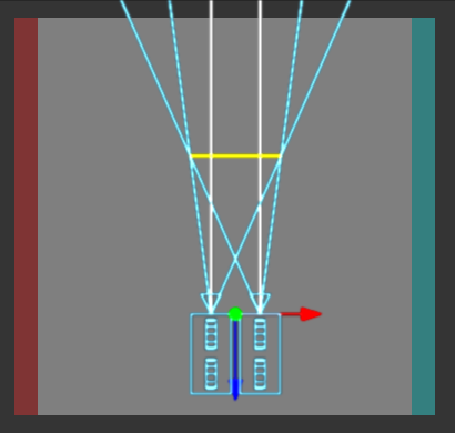
Often regarded the "correct" way to create stereo pairs this is the default method in Fusion. Parallel introduces no vertical parallax, thus creating less "stressful" stereo images.
Defines the distance between the both stereo cameras. If the Eye Separation is set to a value larger than 0, controls for each camera will be shown in the display view when this tool is selected.
This control sets the stereoscopic convergence distance, defined as a point located along the z-axis of the camera which determines where both left and right eye cameras converge.
Film Back
The Film Gate menu shows a list of preset camera types. Selecting one of the options will automatically set the aperture width and aperture height to match the selected camera type.
The Aperture Width and Height sliders control the dimensions of the camera's aperture, or the portion of the camera that lets light in on a real world camera. In video and film cameras, the aperture is the mask opening that defines the area of each frame exposed. Aperture is generally measured in inches, which are the units used for this control.
Determines how the film gate is fit within the resolution gate. This only has an effect when the aspect of the film gate is not the same aspect as the output image. This setting corresponds to the Maya "Fit Resolution Gate". The modes Overscan, Horizontal, Vertical and Fill correspond to Inside, Width, Height and Outside.
- Inside
- The image source will be scaled uniformly until one of it's dimensions (X or Y) fits the inside dimensions of the Mask. Depending on the relative dimensions of image source and Mask Background either the image source's width or height may be cropped to fit the respective dimension of the Mask.
- Width
- The image source will be scaled uniformly until it's width (X) fits the width of the Mask. Depending on the relative dimensions of image source and Mask the image source's Y-dimension might not fit the Mask's Y-dimension, resulting in either cropping of the image source in Y or the image source not covering the Mask's height entirely.
- Height
- The image source will be scaled uniformly until it's height (Y) fits the height of the Mask. Depending on the relative dimensions of image source and Mask the image source's X-dimension might not fit the Mask's X-dimension, resulting in either cropping of the image source in X or the image source not covering the Mask's width entirely.
- Outside
- The image source will be scaled uniformly until one of it's dimensions (X or Y) fits the outside dimensions of the Mask. Depending on the relative dimensions of image source and Mask either the image source's width or height may be cropped or not fit the respective dimension of the Mask.
- Stretch
- The image source will be stretched in X and Y to accomodate the full dimensions of the generated Mask. This might lead to visible distortions of the image source.
Allows to selectively activate the on screen controls that are displayed along with the camera.
- Frustrum
- Displays the actual "viewing cone" of the camera.
- View Vector
- Displays a white line inside the viewing cone which can be used to determine the shift when in parallel mode.
- Near Clip
- The Near clipping plane. This plane can be subdivided for better visibility.
- Far Clip
- The Far clipping plane. This plane can be subdivided for better visibility.
- Plane of Focus
- The Plane of Focus according to the respective slider explained above. This plane can be subdivided for better visibility.
- Convergence Distance
- The point of convergence when using stereo mode. This plane can be subdivided for better visibility.
The Import Camera button displays a dialog to import a camera from another application. It supports the following file types:
- LightWave Scene - .lws
- Max Scene - .ase
- Maya Ascii Scene - .ma
- dotXSI - .xsi
Image
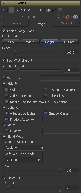
When a 2D image is connected to the Camera, an Image Plane is created that is always oriented so that the image fills the camera's field of view. The Image Plane Tab is hidden until a 2D image is connected to the camera 3D's input on the flow.
With the exception of the controls listed below the options presented in this tab are identical to those presented in the Image Plane tools control tab. Consult that tools documentation for a detailed description.
Use this checkbox to enable or disable the creation of the Image Plane.
Describes how to deal with the input image, if the camera has a different aspect ratio.
- Inside
- The image source will be scaled uniformly until one of it's dimensions (X or Y) fits the inside dimensions of the Mask. Depending on the relative dimensions of image source and Mask Background either the image source's width or height may be cropped to fit the respective dimension of the Mask.
- Width
- The image source will be scaled uniformly until it's width (X) fits the width of the Mask. Depending on the relative dimensions of image source and Mask the image source's Y-dimension might not fit the Mask's Y-dimension, resulting in either cropping of the image source in Y or the image source not covering the Mask's height entirely.
- Height
- The image source will be scaled uniformly until it's height (Y) fits the height of the Mask. Depending on the relative dimensions of image source and Mask the image source's X-dimension might not fit the Mask's X-dimension, resulting in either cropping of the image source in X or the image source not covering the Mask's width entirely.
- Outside
- The image source will be scaled uniformly until one of it's dimensions (X or Y) fits the outside dimensions of the Mask. Depending on the relative dimensions of image source and Mask either the image source's width or height may be cropped or not fit the respective dimension of the Mask.
The Depth slider controls the image plane's distance from the camera.
Projection
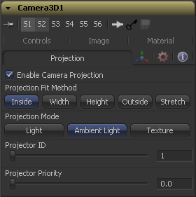
If a 2D image is connected to the camera it becomes possible to project the image into the scene. A projection is different from an Image Plane in that the projection will fall onto the geometry in the scene exactly as if there was a physical projector present in the scene. The image is projected as light, which means the renderer must be set to Enable lighting for the projection to be visible.
See the Projector 3D tool for additional information.
Select this checkbox to enable projection of the 2D image connected to the camera tool.
This button array can be used to select the method used to match the aspect of projected image to the cameras Field of View.
- Light
- Defines the projection as a spotlight.
- Ambient Light
- Defines the projection as an ambient light.
- Texture
- Allows a projection which can be relighted using other lights. Needs a Catcher Tool connected to the appropriate input ports of the specific material.
Notes
Tips for Camera 3D (edit)
- When importing a camera from a 3D application that will also be used as a projector, make sure that the Fit Resolution Gate options on the main Controls tab as well as the Projection tab are in sync. Only the first one will automatically be set to what the 3D app was using. The latter might have to be adjusted manually.
- The camera's image plane isn't just a virtual guide for you in the viewers. It's actual geometry that you can also project onto. You need to use a Replace Material tool after your camera node. See Eric's example comp over at PigsFly or this YouTube video.
- New projection options available since Fusion 6.1:
- The Projector ID can be used to restrict the Catcher tool to certain projectors. The ID doesn't have to be unique amongst all Projector3D or Camera3D tools in your scene.
- The Projector Priority allows you to merge multiple projections on top of each other like 2D images with alpha channels. Set the Catcher's accumulation mode to Blend and define different priorities for each projection. Higher priorities are considered on top of projections that have lower priorities.
- In Fusion 6.1, "parallel" stereo mode assume "Off-axis" in clever stereoscopic terms.
So, to achieve real parallel stereo mode you can:
recipe 1) connect additional external(right) camera to "Right Stereo Camera" input of your camera.
recipe 2) create separate left and right cameras
recipe 3) as workaround you can pull faar-faar away ConvergenceDistance value, something like ConvergenceDistance = 9999999999.
- Try to avoid animate camera AngleOfView parameter. Good idea animate FocalLenght instead AoV, becouse in practice i get unstable behaviour of Fusion, when i use expressions, that operate with camera focalLenght on camera that has AoV animation . Actually may be more general advice is connect your expressions to actual input, that have animation.
If you want to render an image with overscan you also have to modify your scene's Camera3D. Since overscan settings aren't exported along with camera data from 3D applications, this is also necessary for cameras you've imported via .fbx or .ma files. The solution is to increase the film back's width and height by the factor necessary to account for extra pixels on each side. This annotated comp explains the process.
Fusion 7 introduces options to the Renderer3D that allow you to render overscan - either inside the image area or as overscan DoD
| I Am Fusion - Projection Tutorial
This video shows how to align and layer projections using multiple cameras. Watch it on YouTube. |
| The contents of this page are copyright by eyeon Software. |
