Eyeon:Manual/Motion Paths
From VFXPedia
Contents |
Motion Path Introduction
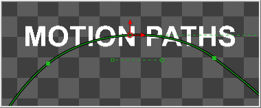
Motion Paths are polylines that apply movement to the positional controls of layers, effects and masks over time. Points can be inserted into any part of the motion path to create any shape imaginable.
Motion paths can only be added to coordinate controls, such as a merge tool's center or published polyline points on a mask. Coordinate controls are represented onscreen with a crosshair or an X.
It is not possible to add a motion path to a single value control, like a blur strength or merge angle.
Types Of Motion Paths
There are two types of Motion Paths; Displacement Paths and XY Paths. A displacement path uses two splines to record the path, one for shape of the path and a displacement spline that represents the timing along the path.
The XY path type employs a spline for the X position of the point and another for the Y Position. The XY paths are explained in detail toward the end of this chapter.
The displacement path is the default type for motion paths, and most documentation in this chapter assumes that this type is used.
Path Modifier
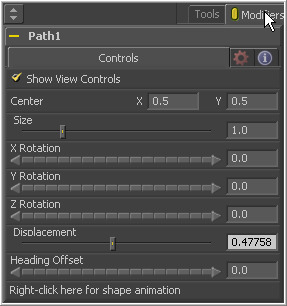
A Path is a Modifier tool. When the path is added to a control, controls for the path will be visible in the modifiers tab of the tool control window.
Displacement Paths
Creating A Displacement Path
To add a motion path to a control, change the current time to the frame where the motion should begin and position the control in its starting position.
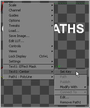
Right-click on the control in the display view and select Set Key Creating Path from the context menu for that control.
The control's text boxes will turn white to indicate that the parameter is now animated and to note that any changes made to the control will cause a new key frame to be created.
The first point of the path will be created and displayed in the view.
To continue adding points, change time and move the control to the location desired for this frame. Fusion will automatically create a keyframe on the motion path at the current time.
A polyline will be drawn from the original keyframe to the new one. The position of the control at frames between the two keyframes is automatically calculated.
Continue adding points by changing time and moving the control until the entire motion path is described.
Upon completion, set the polyline to insert and modify mode by pressing Ctrl-I on the keyboard or pressing the Modify button on the toolbar.
Do not worry too much about the overall shape of the motion path at this point. The shape can be refined further by adding additional points to the polyline.
Displacement Splines And Path Timing
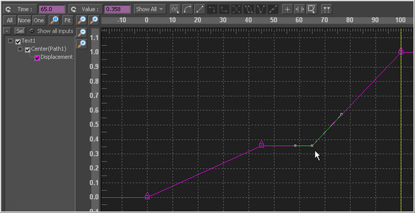
Every motion path has an associated Displacement Spline in the spline editor. The displacement spline represents the position of the animated control along its path, represented as a value between 0.0 and 1.0.
Displacement splines are used to control the speed of a control's movement along its path. To slow down, speed up, stop or even reverse the motion of the control along the path, adjust the values of the points for the path's displacement in the spline editor.
A displacement value of 0.0 in the spline editor indicates that the control is at the very beginning of a path. A value of 1.0 indicates that the control is positioned at the end of the path.
Each locked point on the motion path will have an associated point on the displacement spline. Unlocked points will not have a corresponding point on the displacement spline. Locked and unlocked points are described in more detail below.
Types of Points
Displacement paths in Fusion are composed of Locked and Unlocked Points. Whether a point is locked or not is determined by how it was added to the polyline. Each has a distinct behavior, as described below.
Locked Points
Locked Points are created by changing the current time and moving the animated control when the keypoint is created (as described earlier in Creating A Motion Path). These points indicate that the animated control must be in the specified position at the specified frame.
The locked points are displayed as larger sized hollow squares in the view. Each locked key has an associated point on the path's displacement in the spline editor.
Deleting a locked point from the motion path will change the overall timing of the motion.
Unlocked Points
Unlocked Points are created when additional points are added to the motion path while in insert and modify mode. These points are used to adjust the overall shape of the motion path, without directly affecting the timing of the motion.
Unlocked points do not have corresponding points on the path's displacement spline. They are represented in the views as smaller, solid square points.
To demonstrate the difference between locked and unlocked points, add a text tool to the flow. Type a word in the text tool (or anything else), then position the text's center in the upper left corner of the image.
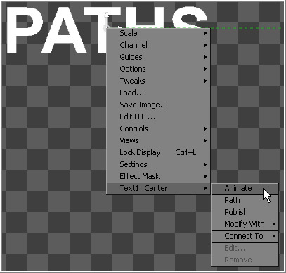
Make certain that the current time is frame 0, right-click on the text cetner and select Animate from the context menu.
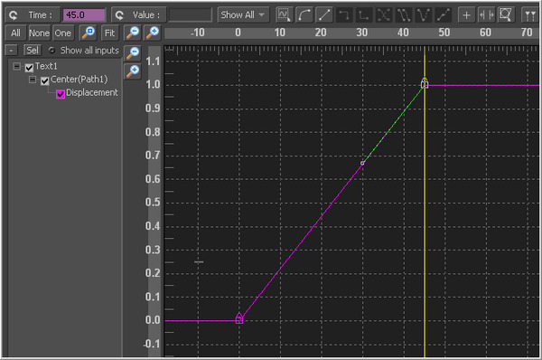
This will create the first locked point of the path. Advance to frame 45 and move the text center to the center of the screen. This sets the second locked point. Display the spline editor to look at the Path 1: Displacement Spline that was created.
At a value of 0.0, the control will be located at the beginning of the path. When the value of the displacement spline is 1.0, the control is located at the end of the path.
Select the keyframe at frame 45 in the displacement spline and move it to frame 50. The motion path is now 50 frames long, without making any changes to the motion path's shape.
Now try to change this point's value from 1.0 to 0.75. It cannot be done because the point is the last in the animation, so the value must be 1.0 in the displacement spline.
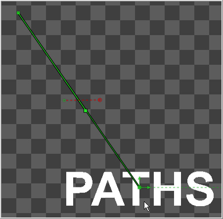
Advance to frame 100 and move the text center to the bottom right corner of the screen. This will create an additional locked point and set a new ending for the path.
Currently, the center is the selected control. Select the motion path spline by using the tab keyboard shortcut to cycle controls until the path is selected, or choose the path using the control's context menu. At the moment, the path is in click append mode. To insert some points, switch the polyline by right-clicking on the path and selecting Insert And Modify from the context menu.
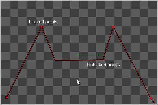
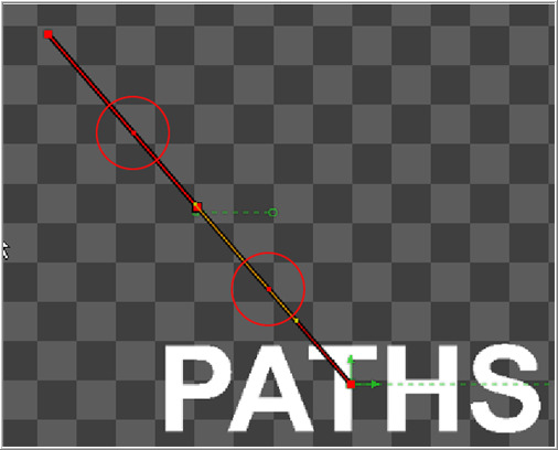
Click on the path and create two new points; one part-way between the first and the second points and the other part-way between the second and the third. Adjust these points so that they are positioned like below.
Look at the spline editor. The two points just added are not present in the motion path's displacement spline. These are unlocked points, used to shape the motion but unrelated to the timing of the path (because the current time was not changed before the points were added). Take advantage of this behavior by making the text stop briefly in the center. Select the point at frame 50 in the displacement spline and hold down the Ctrl key while dragging it to frame 65. The point will be copied at frame 65.
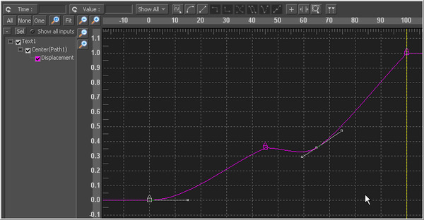
Select the point at frame 0 and at frame 50 and press SHIFT-S while in the spline editor to smooth the displacement curve.
This will cause the motion to accelerate slightly at the beginning and slow to a stop at the center. Render a preview of frames 0 to 100 to see the results so far. Remove the preview when done.
Switch back to working in the view. Delete the unlocked point added between the first point and the middle point. The spline segment of the motion path should become linear.
Deleting this point did not change the amount of time it takes the spline to reach the center of the screen, only the path it takes to get there. Step through a few of the frames in the scene to confirm this.
Now delete the locked point in the center of the screen. Removing this point changes the timing of the animation rather profoundly because the key point in the displacement spline is also removed.
Knowing the difference between locked and unlocked points allows the full power of Fusion's motion paths to be harnessed.
Locking And Unlocking Points
It is possible to change an unlocked point into a locked point, and vice versa, by selecting the point(s) and choosing the Lock Point option from the context menu.
XY Paths
The XY Path type uses a separate spline for the position along the X axis, as it does for the position along the Y axis. To animate a coordinate control using an XY path, right-click on the control and select Modify With>XY Path from the context menu.
At first glance, XY paths work like displacement paths. To describe the path, change frames and position the control where it should be on that frame, then change frames again and move the control to its new position. Fusion automatically interpolates between the points. The difference is that no keyframes are created on the onscreen path.
Look in the spline editor to find the X and Y channel splines. Changes to the controls position will be keyframed on these splines. The advantage to the XY path is that it becomes very easy to work with motion along an individual axis.
Switching Default Paths
Change the Default Path type used when animating a coordinate control to XY path (if this is the preferred type of animation). Open the Global preferences and look under the default's tab for the drop-down list in the default animate section labelled Point With. Change this from the current value to XY Path. The next time Animate is selected from a coordinate control's context menu, an XY path will be used instead of a displacement path.
General Path Techniques
Path Centers
Every motion path has a defined center represented by a crosshair. Path Centers allow paths to be connected to other controls and behave in a hierarchical manor.
A useful example of this technique would be animating the path of a bee in flight. A bee often flies in a constant figure eight pattern while simultaneously moving forward. This would require two paths. The bee would be connected to a first path, which would be a figure eight. This first path's center would be connected to another path defining the forward motion of the bee through the scene.
Copying And Pasting Motion Paths
It is possible to copy an entire motion path to the clipboard and then paste it onto another tool or path.
To copy a motion path, right-click on the path's control header and select Copy from the context menu.
To cut a motion path out of a tool, right-click on the path's control header and select Cut from the context menu.
To paste the copied path over another path, right-click on the path's control header and select Paste from the context menu. The settings of the old motion path will be overwritten with the settings of the one in the clipboard.
Removing Motion Paths
To remove a control from a motion path, right-click on the motion path's control header and select Delete from the motion path's context menu. Alternately, right-click on the animated control and select Remove From Path X: Value.
Recording
Using this mode allows both of the control's spatial and temporal information to be animated at the same time. This is useful when both position and speed are crucial to achieve the desired result.
Right-click on the desired path to display its context menu and select Record from the context menu. This displays a submenu of available data that may be recorded.
Use the Record Time option in conjunction with the Draw Append mode to create complex motion paths that will recreate the motion precisely as the path is drawn.
The time used to record the animation may not suite the needs of a project precisely. Adjust the path's displacement spline in the spline editor to more correctly match the required motion.
