Projection Type
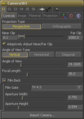
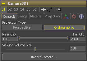
Use the Projection Type button to choose between Perspective and Orthographic cameras. Generally, real world cameras are perspective cameras. An orthographic camera uses parallel orthographic projection, a technique where the view plane is perpendicular to the viewing direction. This produces a parallel camera output that is undistorted by perspective.
Orthographic cameras only present controls for the near and far clipping planes, and a control to set the viewing volume.
Near/Far Clip
By default the Clipping planes for the camera are determined automatically (see Adaptively Adjust Near/Far Clip control below). When Adaptive clipping is disabled, this control becomes active.
The Near Clip and Far Clip range control is used to determine the size of the clipping plane. A clipping plane determines how close to the camera or how far away from the camera an object must be before it is no longer rendered or seen by the camera.
The values are expressed in units, so a far clipping plane of 20 means that any object more than 20 units distant from the camera will be invisible to the camera. A near clipping plane of 0.1 means that any object closer than 0.1 units will also be invisible.
Note that a smaller range between the near and far clipping planes allows greater accuracy in all depth calculations. If you experience any artifacting on distant objects, try increasing the depth of the Near Clip plane.
Adaptively Adjust Near/Far Clip
When selected the renderer will automatically adjust the cameras near/far clipping plane to match the extents of the scene. This setting overrides the values of the Near and Far clip range control described above. This option is not available for Orthographic cameras.
Viewing Volume Size
The Viewing Volume Size control only appears when the Projection Type is set to Orthographic. It determines the size of the box that makes up the camera's field of view.
The Z distance of an orthographic camera from the objects it sees does not affect the scale of those objects, only the viewing size does.
Angle Of View Type
Use the Angle of View Type button array to choose how the camera's angle of view is measured. Some applications use vertical measurements, some use horizontal and others use diagonal measurements.
Angle Of View
Angle Of View defines the area of the scene that can be viewed through the camera. Generally, the human eye can see much more of a scene than a camera, and various lenses record different degrees of the total image. A large value produces a wider angle of view and a smaller value produces a narrower, or more tightly focused, angle of view.
The angle of view and focal length controls are directly related. Smaller focal lengths produce a wider angle of view, so changing one control automatically changes the other to match.
Focal Length
In the real world, a lens' Focal Length is the distance from the center of the lens to the film plane. The shorter the focal length, the closer the focal plane is to the back of the lens. The focal length is measured in millimeters. The angle of view and focal length controls are directly related. Smaller focal lengths produce a wider angle of view, so changing one control automatically changes the other to match.
The relationship between focal length and angle of view is: angle = 2 * arctan[aperture / 2 / focal_length]
Use the vertical aperture size to get the vertical angle of view, and the horizontal aperture size to get the horizontal angle of view.
Film Back
Film Gate
The Film Gate menu shows a list of preset camera types. Selecting one of the options will automatically set the aperture width and aperture height to match the selected camera type.
Aperture Width/Height
The Aperture Width and Height sliders control the dimensions of the camera's aperture, or the portion of the camera that lets light in on a real world camera. In video and film cameras, the aperture is the mask opening that defines the area of each frame exposed. Aperture is generally measured in inches, which are the units used for this control.
Import Camera
The Import Camera button displays a dialog to import a camera from another application. Supported filetypes are Alias's Maya .ma files, 3ds Max ASCII Scene Export, NewTek's LightWave .lws and Softimage XSI's .xsi.
For more details, see the Eyeon:Manual/3D Tools chapter.
Image Plane Tab
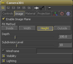
When a 2D image is connected to the Camera, an Image Plane is created that is always oriented so that the image fills the camera's field of view. The Image Plane Tab is hidden until a 2D image is connected to the camera 3D's input on the flow.
See the documentation for the Image Plane tool for a description of the other controls found in this tab.
Enable Image Plane
Use this checkbox to enable or disable the creation of the Image Plane
Depth
The Depth slider controls the image plane's distance from the camera.
Projection Tab
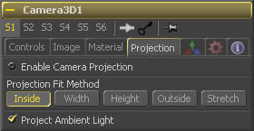
If a 2D image is connected to the camera it becomes possible to project the image into the scene. A projection is different from an Image Plane in that the projection will fall onto the geometry in the scene exactly as if there was a physical projector present in the scene. The image is projected as light, which means the renderer must be set to Enable lighting for the projection to be visible.
See the Projector 3D tool for additional information.
Enable Camera Projection
Select this checkbox to enable projection of the 2D image connected to the camera tool.
Projection Fit Method
This button array can be used to select the method used to match the aspect of projected image to the cameras Field of View.
Project Ambient Light
Normally the projection is diffuse/specular light, which is directional. Selecting this checkbox makes the light from the projection ambient instead.
Materials Tab
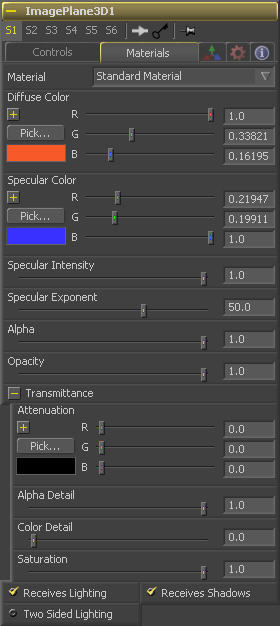
Material: Standard Material
This menu is reserved for future use. At the time of writing the Material drop down box contains only a Standard Material. Additional materials are being added in Fusion 6.
Diffuse Color
Diffuse Color is the basic color of an object when lit indirectly, without specularity (highlights).
Specular Color
Specular Color determines the color of light that reflects from a shiny surface. The more specular a material is, the glossier it appears. Surfaces like plastics and glass tend to have white specular highlights, whereas metallic surfaces like gold have specular highlights that tend to inherit their color from the material color.
Specular Intensity
Specular Intensity controls how hot or large the specular highlight is.
Specular Exponent
Specular Exponent controls the falloff of the specular highlight. The smaller the value, the sharper the falloff, and the smoother & glossier the material appears.
Alpha
This slider sets the material's Alpha channel value. This affects diffuse and specular colors equally, and affects the alpha value of the material in the rendered output.
Opacity
Reducing the material's Opacity will decrease the color and alpha values of the specular and diffuse colors equally, making the material transparent and allowing hidden objects to be seen through the material.
Transmittance
Transmittance controls the way light passes through a material. For example, a solid blue pitcher will cast a black shadow, but one made of translucent blue plastic would cast a much lower density blue shadow.
There is a separate opacity option. Opacity determines how transparent the actual surface is when it is rendered. Fusion allows for adjusting both opacity and transmittance separately. This might be a bit counter-intuitive to artists who are unfamiliar with 3D software at first. It is possible to have a surface that is fully opaque but transmits 100% of the light arriving upon it (so, in a sense, it is actually a luminous/emissive surface).
Alpha Detail
When the Alpha Detail slider is set to 0, the alpha channel of the object is ignored and the entire object casts a shadow. If it is set to 1, the alpha channel detemines what portions of the object cast a shadow.
Color Detail
The Color Detail slider modulates light passing through the surface by the diffuse color + texture colors. Use this to throw a shadow that contains color details of the texture applied to the object. Increasing the slider from 0 to 1 brings in more of diffuse color + texture color into the shadow. Note that the alpha and opacity of the object is ignored when transmitting color, allowing an object with a solid alpha to still transmit its color to the shadow.
Transmission Color
Transmission Color determines how much color is passed through the object. For an object to have transmissive shadows, set the transmittance color to (1, 1, 1), which means 100% of green, blue, red light pass through the object. Setting this color to RGB (1, 0, 0) means that the material will transmit 100% of the red arriving at the surface but none of the green or blue light. This allows for 'stained glass' shadows.
Saturation
The Saturation slider controls the saturation of the color component transmitted to the shadow. Setting this to 0.0 will result in monochrome shadows.
Receives Lighting/Shadows
These checkboxes control whether the material is affected by lighting and shadows in the scene. If turned off, the object will always be fully lit and/or unshadowed.
Two Sided
This makes the surface effectively two-sided by adding a second set of normals facing the opposite direction on the back side of the surface. This is normally off, to increase rendering speed, but can be turned on for 2D surfaces or for objects that are not fully enclosed, to allow the reverse or interior surfaces to be visible as well.
Normally, in a 3D application only the front face of a surface is visible and the back face is culled, so that if a camera were to revolve around a plane in a 3D application when it reached the backside, the plane would become invisible. Making a plane two sided in a 3D application is equivalent to adding another plane ontop of the first but rotated by 180 degrees so the normals are facing the opposite direction on the backside. Thus, when you revolve around the back, you see the second image plane which has its normals facing the opposite way.
Fusion does exactly the same thing as 3D applications when you make a surface two sided. The confusion about what two-sided does arises because Fusion does not cull backfacing polygons by default. If you revolve around a one-sided plane in Fusion you will still see it from the backside (but you are seeing the frontside bits duplicated through to the backside as if it were transparent). Making the plane two sided effectively adds a second set of normals to the backside of the plane.
Note this can become rather confusing once you make the surface transparent, as the same rules still apply and produce a result which is counterintuitive. If you view from the frontside a transparent two-sided surface illuminated from the backside, it will look unlit.
In Fusion 5.1 and earlier this control was called "Two Sided Lighting" but this confused users so the name was changed.
3D Transformation Tab
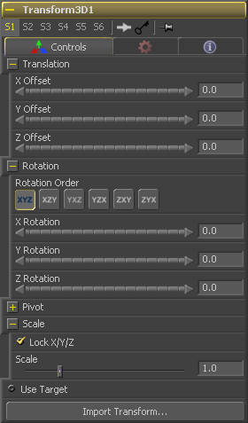
On Screen : Transformation Widget
Most of the controls in this tab are represented in the display view by a Transformation Widget with modes for transformation, rotation and scaling. To change the mode of the widget, select one of the three buttons in the toolbar along the side of the view, or press the `q' key for translation mode, `w' for rotation and `e' for scaling. In all three modes, individual axes of the control may be dragged to affect just that axis, or the center of the control may be dragged to affect all three axes. Note: In order to scale in a single dimension, the Lock X/Y/Z Scale checkbox must be unchecked.
X, Y, Z Offset
These controls can be used to position the 3D element.
Rotation Order
Use these buttons to select which order is used to apply the Rotation along each axis of the object. For example, XYZ would apply the rotation to the X axis first, followed by the Y axis and then followed by the Z axis.
X, Y, Z Rotation
Use these control to rotate the object around its pivot point. If the Use Target checkbox is selected then the rotation is relative to the position of the target, otherwise the global axis is used.
X, Y, Z Pivot
A Pivot point is the point around which an object rotates. Normally, an object will rotate around its own center, which is considered to be a pivot of 0,0,0. These controls can be used to offset the pivot from the center.
X, Y, Z Scale
If the Lock X/Y/Z checkbox is checked, a single Scale slider will be shown. This adjusts the overall size of the object. If the Lock checkbox is unchecked, individual X, Y and Z sliders will be displayed to allow scaling in any dimension. Note: If the Lock checkbox is checked, scaling of individual dimensions is not possible, even when dragging specific axes of the Transformation Widget in scale mode.
Use Target
Selecting the Use Target checkbox enables a set of controls for positioning an XYZ target. When target is enabled, the object will always rotate to face the target. The rotation of the object becomes relative to the target.
Tips for Camera 3D (edit)
Soft particle clipping with pCustom (Last Updated: Month 7th, 2006)
Particles just disappear when they intersect the clipping plane of the camera. This causes a visible pop in the image which can be distracting. This tip demonstrates how the pCustom tool can be used to create a soft clip region for the camera, by fading out the particles before they reach the clipping plane.
While this is a particles example, it does effectively demonstrate the use of the camera with 3D particles, as well as the effect of the cameras clipping plane on the scene.
Importing 3D cam tip
I just wanted share sth which saved me some time and it's connected with
importing 3D cam.
Basically i have camera with animation done in maya. When i imported camera
into fusion it didn't match - there was an offset even in the first frame!
after reading the vfxpedia faq i came across fact that fusion "internally fits
the film gate to the resolution gate vertically" - that was my case. In maya i
have "fit resolution gate" set to "horizontal" which was the reason for the
offset.
However when i changed Film Gate in fusion Camera options from "user" to
Academy (Regular 35), "magically" everything matched!! :D and i Dont have to
re-render and re-animate stuff in 3D :)
--Marek
