Eyeon:Manual/Fusion 6/Interface Overview/Flow Editor/Connecting and Disconnecting Tools
From VFXPedia
[ Main Manual Page ]
- Flow Overview
- Viewing, Scaling and Panning the Flow
- Context Menus
- Adding Tools
- Connecting and Disconnecting Tools
- Inserting Tools
- Replacing Tools
- Deleting Tools
- Connection Types
- Moving Tools and Organizing the Flow
- Groups
- Displaying Tile Pictures
- Viewing Tools
- Tooltips and the Status Bar
- Copying and Pasting Tools
- Instancing Tools
- Finding Tools
- Macro Tools
- Flow Options
- Tool Context Menu
- Tool Tile Color Coding and Icons
Contents |
Connecting And Disconnecting Tools
Each tool in a project has its own tile in the flow. These tiles show the inputs and output for the tool as small colored nodes attached to the tile. The arrow-shaped nodes represent the image inputs, and the grey or red square nodes represent the tool's processed output.
A tool must have at least one output node. It generally also requires one input node, unless it is a creator tool. Almost all tools also have at least one mask input, which is usually colored blue. A tool cannot have more than one output. A classic example of a multi-input tool is Merge, which has a background input, a foreground input, and a mask input.
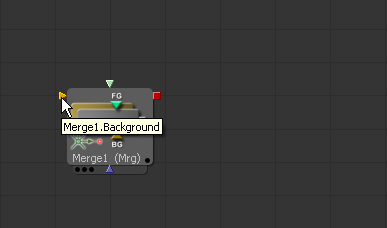
Hold the mouse pointer over a tool's input for a moment and a small pop-up containing the input's name will appear.
Connecting Tools
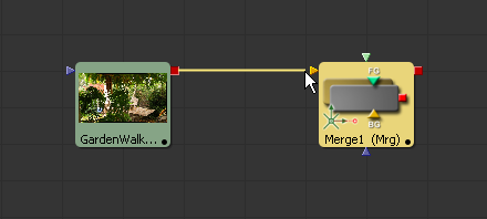
Build a flow by connecting tools together using the inputs and outputs. For example, to connect the output of a background tool to a color corrector tool, click on the output node of the Background tool and drag the connection over the input node of the Color Corrector. A small line, or pipe, will be drawn between these two nodes to represent the connection.
Disconnecting Tools
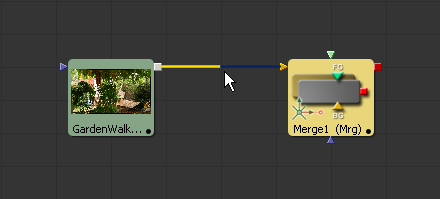
The pipe between two tools is divided into two halves; the output half and the input half. To disconnect a tool's inputs or output, click on the input half of the connection pipe or click on the input arrow itself and drag to pull the connection away from the tool.
An entire tool can be disconnect by holding down the Shift key while moving the tool. If the Shift key is depressed when letting go of the tool, all existing connections to that tool will be removed.
Replacing Connections
To replace an existing connection on a tool with another one, simply drag the new connection over the existing one.
Tracing Pipes Through The Flow
Several visual cues exist to help you follow the pipes through the flow. As an option pipes can always been drawn on top of any other tools.
Placing the mouse over a specific tool will cause the pipes connected to that tool to become highlighted. Placing the mouse directly over a pipe will cause a tooltip to appear with details on its source output and destination input.
Branching
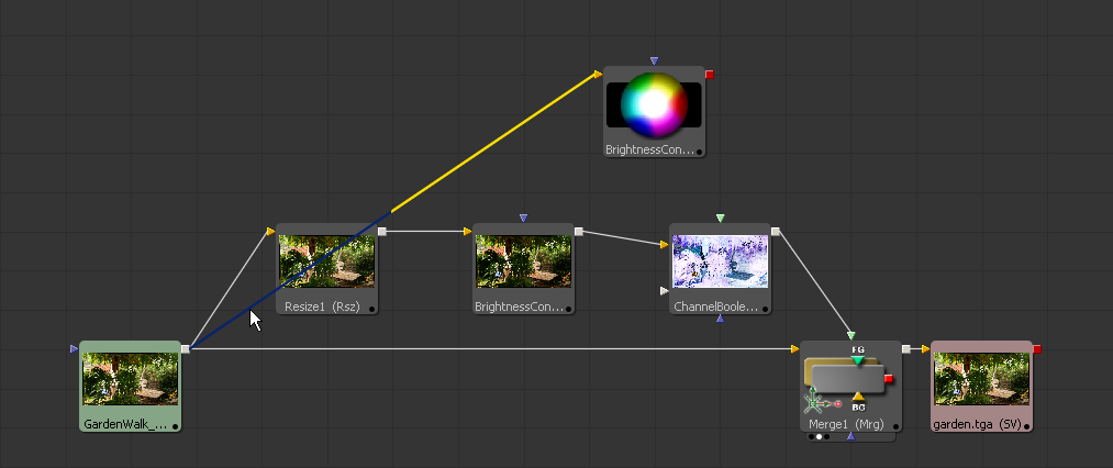
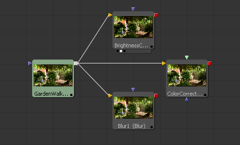
The output of any given tool can be connected to multiple inputs on other tools, which is a feature in Fusion called branching. Branching permits a single image to be separately processed by two or more streams of tools.
Only one connection per input is allowed but a tool output can have any number of branches and outbound connections.