Eyeon:Manual/Fusion 6/Common 3D Controls
From VFXPedia
[ Main Manual Page ]
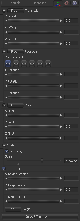
There are two tabs which are present on nearly every one of the 3D category of tools. Specifically, the Transform tab contain controls necessary for manipulating the position of an object in 3D space, while the Material tab contains controls used to defining the basic material and surface characteristics.
Rather than repeat the same information for each tool the documentation for these controls have been consolidated into this page.
3D Transform Tab
Translation
Left-Click and hold on this button allows to pick XYZ-Coordinates from any 3D Scene or 2D image containing XYZ values like a rendered worldpass to re-position your object. When picking from a scene make sure to view a tool which is upstream from the tool you want to change position for. Picking from a view that also shows the object you're picking for might lead to incorrect behavior because the position values of the actual object are interfering with the rest of the scene. When picking from a 2D image make sure it's rendered in 32bit float to get full precision.
These controls can be used to position the 3D element.
Rotation
Left-Click and hold on this button allows to pick rotational values from any 3D Scene or 2D image containing those values like a XYZ-Normal-Pass to re-orient your object. When picking from a scene make sure to view a tool which is upstream from the tool you want to change rotation for. Picking from a view that also shows the object you're picking for might lead to incorrect behavior because the rotational values of the actual object are interfering with the rest of the scene. When picking from a 2D image like an XYZ-Normal-pass make sure it's rendered in 32bit float and WorldSpace coordinates to get full precision and the correct rotational values.
Use these buttons to select which order is used to apply Rotation along each axis of the object. For example, XYZ would apply the rotation to the X axis first, followed by the Y axis and then finally the Z axis.
Use these control to rotate the object around its pivot point. If the Use Target checkbox is selected then the rotation is relative to the position of the target, otherwise the global axis is used.
Pivot Controls
A Pivot point is the point around which an object rotates. Normally, an object will rotate around its own center, which is considered to be a pivot of 0,0,0. These controls can be used to offset the pivot from the center.
Scale
If the Lock X/Y/Z checkbox is checked, a single Scale slider will be shown. This adjusts the overall size of the object. If the Lock checkbox is unchecked, individual X, Y and Z sliders will be displayed to allow individual scaling in each dimension. Note: If the Lock checkbox is checked, scaling of individual dimensions is not possible, even when dragging specific axes of the Transformation Widget in scale mode.
Selecting the Use Target checkbox enables a set of controls for positioning an XYZ target. When target is enabled, the object will always rotate to face the target. The rotation of the object becomes relative to the target.
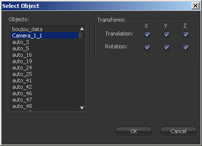
Opens a file browser where you can select a scene file saved or exported by your 3d application. It supports the following file types:
- LightWave Scene - .lws
- Max Scene - .ase
- Maya Ascii Scene - .ma
- dotXSI - .xsi
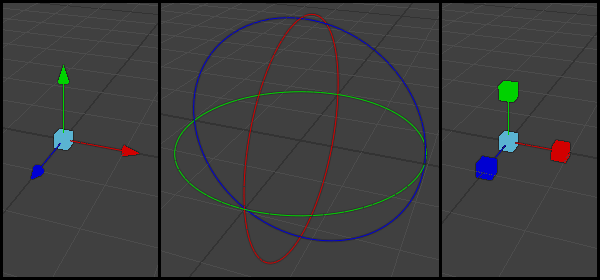
Most of the controls in this tab are represented in the display view by a Transformation Widget with modes for transformation, rotation and scaling. To change the mode of the widget, select one of the three buttons in the toolbar along the side of the view. The modes can also be toggled using the keyboard shortcut q for translation, w for rotation and e for scaling. In all three modes, individual axes of the control may be dragged to affect just that axis, or the center of the control may be dragged to affect all three axes.
3D Material Tab
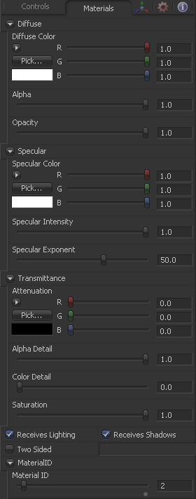
The controls in the material tab are used to determine the appearance of the 3D object when lit. Most of these controls directly affect how the object interacts with light. The controls in this tab represent a basic shader with a limited range of controls. For more advanced control over the objects appearance Fusion provides a wide range of 3D Material tools which can be used to assemble a more finely detailed and precise shader.
When a shader is constructed using the 3D Material tools and connected to the 3D Objects material input the controls in this tab will disappear, to be replaced by a label that indicates that an external material is currently in use.
Diffuse
Diffuse describes the base surface characteristics without any additional effects like reflections or specular highlights.
The Diffuse Color determines the basic color of an object when the surface of that object is either lit indirectly or lit by an ambient light. If a valid image is provided to the tools diffuse texture input, then the RGB values provided here will also be multiplied by the color values of the pixels in the diffuse texture. The alpha channel of the diffuse material can be used to control the transparency of the surface.
This slider sets the material's Alpha channel value. This affects diffuse and specular colors equally, and affects the alpha value of the material in the rendered output. If the tools diffuse texture input is used then the Alpha value provided here is multiplied by the alpha channel of the pixels in the image.
Reducing the material's Opacity will decrease the color and alpha values of the specular and diffuse colors equally, making the material transparent and allowing hidden objects to be seen through the material.
Specular
The Specular section provides controls for determining the characteristics of light which reflects towards the viewer. These controls affect the appearance of the specular highlight which appears on the surface of the object.
Specular Color determines the color of light that reflects from a shiny surface. The more specular a material is, the glossier it appears. Surfaces like plastics and glass tend to have white specular highlights, whereas metallic surfaces like gold have specular highlights that tend to inherit their color from the material color. The basic shader material does not provide an input for textures to control the specularity of the object. Use tools from the 3D Material category when more precise control is required over the specular appearance.
Specular Intensity controls how strong the specular highlight is. If the specular intensity texture input has a valid connection, then this value is multiplied by the alpha value of the input.
Specular Exponent controls the falloff of the specular highlight. The greater the value, the sharper the falloff, and the smoother & glossier the material appears. The basic shader material does not provide an input for textures to control the specular exponent of the object. Use tools from the 3D Material category when more precise control is required over the specular exponent.
Transmittance
Transmittance controls the way light passes through a material. For example, a solid blue sphere will cast a black shadow, but one made of translucent blue plastic would cast a much lower density blue shadow.
There is a separate opacity option. Opacity determines how transparent the actual surface is when it is rendered. Fusion allows for adjusting both opacity and transmittance separately. This might be a bit counter-intuitive to artists who are unfamiliar with 3D software at first. It is possible to have a surface that is fully opaque but transmits 100% of the light arriving upon it, effectively making it a a luminous / emissive surface.
Attenuation determines how much color is transmitted through the object. For an object to have transmissive shadows, set the attenuation to (1, 1, 1), which means 100% of green, blue, red light pass through the object. Setting this color to RGB (1, 0, 0) means that the material will transmit 100% of the red arriving at the surface but none of the green or blue light. This allows for 'stained glass' shadows.
When the Alpha Detail slider is set to 0, the alpha channel of the object is ignored and the entire object casts a shadow. If it is set to 1, the alpha channel determines what portions of the object cast a shadow.
The Color Detail slider modulates light passing through the surface by the diffuse color + texture colors. Use this to throw a shadow that contains color details of the texture applied to the object. Increasing the slider from 0 to 1 brings in more of diffuse color + texture color into the shadow. Note that the alpha and opacity of the object is ignored when transmitting color, allowing an object with a solid alpha to still transmit its color to the shadow.
The Saturation slider controls the saturation of the color component transmitted to the shadow. Setting this to 0.0 will result in monochrome shadows.
These checkboxes control whether the material is affected by lighting and shadows in the scene. If turned off, the object will always be fully lit and/or unshadowed.
This makes the surface effectively two-sided by adding a second set of normals facing the opposite direction on the back side of the surface. This is normally off, to increase rendering speed, but can be turned on for 2D surfaces or for objects that are not fully enclosed, to allow the reverse or interior surfaces to be visible as well.
Normally, in a 3D application only the front face of a surface is visible and the back face is culled, so that if a camera were to revolve around a plane in a 3D application when it reached the backside, the plane would become invisible. Making a plane two sided in a 3D application is equivalent to adding another plane on top of the first but rotated by 180 degrees so the normals are facing the opposite direction on the backside. Thus, when you revolve around the back, you see the second image plane which has its normals facing the opposite way.
Fusion does exactly the same thing as 3D applications when you make a surface two sided. The confusion about what two-sided does arises because Fusion does not cull backfacing polygons by default. If you revolve around a one-sided plane in Fusion you will still see it from the backside (but you are seeing the frontside bits duplicated through to the backside as if it were transparent). Making the plane two sided effectively adds a second set of normals to the backside of the plane.
Note this can become rather confusing once you make the surface transparent, as the same rules still apply and produce a result which is counter-intuitive. If you view from the frontside a transparent two-sided surface illuminated from the backside, it will look unlit.
Material ID
This control is used to set the numeric identifier assigned to this material. The Material ID is an integer number that will be rendered into the MatID auxiliary channel of the rendered image when the Material ID option is enabled in the Renderer 3D tool. See the Material and Object ID section in the 3D chapter for more information.
Tips for Common 3D Controls (edit)
| The contents of this page are copyright by eyeon Software. |


