Eyeon:Manual/Tool Reference/3D/Projector 3D
From VFXPedia
Projector 3D [3Pr] | |
|
The Projector 3D tool is used to project an image upon 3D geometry. This can be useful in many ways; texturing objects with multiple layers, applying a texture across multiple separate objects, projecting background shots from the camera's viewpoint, image-based rendering techniques and much more. Projected textures can be allowed to "slide" across the object, if the object moves relative to the Projector3D, or alternatively, by grouping the two together with a Merge 3D they can be moved as one, and the texture will remain locked to the object. | |
Contents |
The Projector 3D tool's capabilities and restrictions are best understood if the Projector is considered to be a superset of the Spotlight tool. The fact that the Projector3D tool is actually a light has several important consequences:
- Lighting must be turned on for the results of the projection to be visible.
- The light emitted from the projector is treated as diffuse/specular light. This means that it will be affected by the surface normals and can cause specular highlights. If this is undesirable, set Projector 3D to project into the ambient light channel.
- Enabling shadows will cause Projector 3D to cast shadows.
- Just as with other lights, the light emitted by a Projector 3D will only affect objects that feed into the first Merge 3D that is downstream of the Projector 3D tool on the flow. Enabling Merge 3D's Pass Through Lights checkbox will allow the projection to light objects further downstream.
- The light emitted by a Projector 3D is controlled by the Lighting Options settings on objects and the Receives Lighting options on materials.
- Alpha values cannot be projected.
- If two projections overlap, their light contributions will be added together.
The Camera 3D tool can also be used to do projection, and gives you detailed control over aperture, film back, and clip planes, for better matching of projections with existing footage. Projector 3D was designed more as a custom light in 3D scenes (such as a spotlight with a custom cone shape), and instead allows you to specify light intensity, color, decay and shadows.
Note: When using projectors in an OpenGL view or in the OpenGL Renderer the lighting must be set to per-pixel (the default) in order to see the results of the projection in the main view. Note that the per-pixel lighting mode requires a certain level of shader support from your graphics card (ie. DX9 level or higher graphics card - generally a GeForce 5000 line or newer, Radeon 9000 line or newer will work.) Even if you cannot see the projection in the GL view, you can still always see it the software renderer.
The Projector3D tool was added to Fusion in version 5.1.
Controls Tab
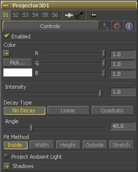
When this checkbox is selected the projector's light affects the scene. Clear the checkbox to turn off the light.
Use this standard color control to tint the color of the projected light.
Use this slider to set the intensity of the light emitted by the projector.
A projector defaults to No Falloff, meaning that its light has equal intensity on geometry regardless of the distance from the light to the geometry. To cause the intensity to falloff with distance, set the Decay type either to Linear, or Quadratic modes.
The cone angle of the projector. It may not be set higher than 180 degrees. The cone of the projector is always square - if you want to project a rectangular region you'll need to pad the image you want to project until it is square and/or use the FitMethod control.
The Fit Method determines how the projection is fit within the projection cone.
The first thing to know is that although this documentation may call it a 'cone', the Projector3D tool and the Camera3D tools do not project actual cones - its more of a pyramid of light with its apex at the camera/projector. The Projector3D tool always projects a square pryamid of light, ie. its X and Y angles of view are the same. The pyramid of light projected by the Camera3D tool can be non-square depending on what the Film Back is set to in the camera. Note that the aspect of the image connected into the Projector3D/Camera3D does not affect the X/Y angles of the pyramid, but rather the image is scaled to fit into the pyramid based upon the fit options.
When both the aspect of the pyramid (AovY/AovX) and the aspect of the image (height * pixelAspectY) / (width * pixelAspectX) are the same, there is no need for the fit options and in this case the fit options all do the same thing. However, when the aspect of the image and the pyramid (as determined by the Film Back settings in Camera3D) are different the fit options become important.
For example, if you pick 'Fit by Width', this will make the width of the image fit across the width of the Camera3D pyramid. In this case, if the image has a greater aspect ratio than the aspect of the pyramid, some of the projection will extend vertically outside of the pyramid.
There are five options:
- Inside - The image is uniformly scaled so that its largest dimension fits inside of the cone. Another way to think about this, is that it scales the image as big as possible subject to the restriction that the *image* is fully contained within the pyramid of the light. This means, for example, that nothing outside the pyramid of light will ever receive any projected light.
- Width - The image is uniformly scaled so that its width fits inside the cone. Note the image could still extend outside of the cone in its height direction.
- Height - The image is uniformly scaled so that its height fits inside the cone. Note the image could still extend outside of the cone in its width direction.
- Outside - The image is uniformly scaled so that its smallest dimension fits inside of the cone. Another way to think about this is that it scales the image as small as possible subject to the restriction that the image covers the entire pyramid (ie. the *pyramid* is fully contained within the image) This means that any pixel of any object inside the pyramid of light will always get illuminated.
- Stretch - The image is non-uniformly scaled so it exactly covers the cone of the projector.
Normally the Projector3D tool projects diffuse/specular light, which is directional. Selecting this checkbox makes the light from the projection ambient instead.
Shadow Controls
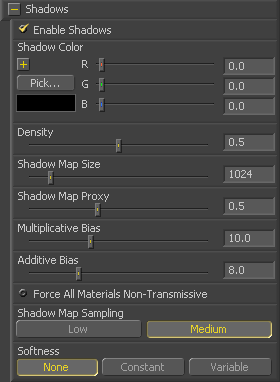
The Enable Shadows checkbox should be selected if the light is to produce shadows. This defaults to selected.
Use this standard Color control to set the color of the shadow. This defaults to black (0, 0, 0).
The shadow Density determines how opaque the shadow will be. A density of 1.0 will produce a completely transparent shadow, whereas lower values make the shadow transparent.
The Shadow Map Size control determines the size of the bitmap used to create the shadow map. Larger values will produce more detailed shadow maps at the expense of memory and performance.
Shadow Map Proxy determines the size of the shadow map used for proxy and auto proxy calculations. A value of 0.5 would use a 50% shadow map.
Shadows are essentially textures applied to objects in the scene so there will occasionally be z-fighting, where the portions of the object that should be recieving the shadows render over top of the shadow instead. An example of Z-fighting is shown below.
Biasing works by adding a small depth offset to move the shadow away from the surface it is shadowing, eliminating the z-fighting. Too little bias and the objects can self-shadow themselves. Too much bias and the shadow can become separated from the surface.
Make adjustments to the Multiplicative Bias first, then fine tune the result using the Additive Bias control.
Normally, a RGBAZ shadowmap is used when rendering shadows. By enabling this option you are forcing the renderer to use a Z only shadowmap. This can result in significantly faster shadow rendering while using a fifth as much memory. The disadvantage is that you can no longer cast 'stained-glass' like shadows.
Soft edges in shadows are produced by filtering the shadowmap when it is sampled. Fusion has three separate filtering methods available when rendering shadows which produce different effects.
- None - Shadows will have a hard edge. No filtering of the shadowmap is done at all. The advantage of this method is that you only have to sample one pixel in the shadowmap so it is fast.
- Constant - Shadows edges will have a constant softness. A filter with a constant width is used when sampling the shadowmap. The size of the filter is controlled by adjusting the Constant Softness slider. Note that the larger you make the filter, the longer that it will take to render the shadows.
- Variable - The softness of shadow edges will grow the further away the shadow receiver is from the shadow caster. The variable softness is achieved by changing the size of the filter based on the distance between the receiver and caster. When this option is selected, the Softness Falloff, Min Softness and Max Softness sliders appear.
If the Softness is set to constant, then this slider will appear. It can be used to set the overall softness of the shadow.
The Softness Falloff slider appears when the Softness is set to variable. This slider controls how fast the softness of shadow edges grows with distance. To be more precise, it controls how fast the shadowmap filter size grows based upon the distance between shadow caster and receiver. Its affect is mediated by the values of the min and max softness sliders.
The Min Softness slider appears when the Softness is set to variable. This slider controls the Minimum Softness of the shadow. The closer the shadow is to the object casting the shadow, the sharper it will be up to the limit set by this slider.
The Max Softness slider appears when the Softness is set to variable. This slider controls the Maximum Softness of the shadow. The further the shadow is from the object casting the shadow, the softer it will be up to the limit set by this slider.
3D Transformation Tab
On Screen : Transformation Widget
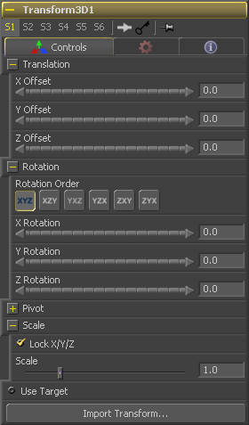
Most of the controls in this tab are represented in the display view by a Transformation Widget with modes for transformation, rotation and scaling. To change the mode of the widget, select one of the three buttons in the toolbar along the side of the view, or press the `q' key for translation mode, `w' for rotation and `e' for scaling. In all three modes, individual axes of the control may be dragged to affect just that axis, or the center of the control may be dragged to affect all three axes. Note: In order to scale in a single dimension, the Lock X/Y/Z Scale checkbox must be unchecked.
These controls can be used to position the 3D element.
Use these buttons to select which order is used to apply the Rotation along each axis of the object. For example, XYZ would apply the rotation to the X axis first, followed by the Y axis and then followed by the Z axis.
Use these control to rotate the object around its pivot point. If the Use Target checkbox is selected then the rotation is relative to the position of the target, otherwise the global axis is used.
A Pivot point is the point around which an object rotates. Normally, an object will rotate around its own center, which is considered to be a pivot of 0,0,0. These controls can be used to offset the pivot from the center.
If the Lock X/Y/Z checkbox is checked, a single Scale slider will be shown. This adjusts the overall size of the object. If the Lock checkbox is unchecked, individual X, Y and Z sliders will be displayed to allow scaling in any dimension. Note: If the Lock checkbox is checked, scaling of individual dimensions is not possible, even when dragging specific axes of the Transformation Widget in scale mode.
Selecting the Use Target checkbox enables a set of controls for positioning an XYZ target. When target is enabled, the object will always rotate to face the target. The rotation of the object becomes relative to the target.
| The contents of this page are copyright by eyeon Software. |


