< Previous | Contents | Next >
LUT Cube Analyzer controls
Controls Tab
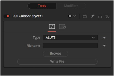
The Controls tab for the LUT Cube Analyzer node is used to select the desired LUT output format, specify a filename, and write the 3D LUT to disk.
Select the desired output format of the 3D LUT.
Enter the path where you want the file saved and enter the name of the LUT file. Alternatively, you can click the Browse button to open a file browser to select the location and filename.
Press this button to generate the 3D LUT file based on the settings above.
Settings Tab
![]()
The Settings tab in the Inspector is also duplicated in other LUT nodes. These common controls are described in detail at the end of this chapter in “The Common Controls” section.
LUT Cube Apply [LCP]
The LUT Cube Apply node
LUT Cube Apply Node Introduction
The LUT Cube Apply node takes an image created by the LUT Cube Creator as the foreground input and applies that LUT to the image connected to the background input.
Feeding the original image into the node would result in an unaltered, or 1:1, output.
You can, however, modify, grade, and color correct the original cube image with as many nodes as you like and feed the result into the LUT Cube Apply. Or, take a LUT image that has been graded beforehand to apply the LUT without having to write an actual 3D LUT using the LUT Cube Analyzer.
Inputs
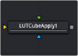
The LUT Cube Apply has three inputs: a green input where the output of the LUT Cube Creator is connected, an orange input for the image to have the LUT applied, and a blue effect mask input
— Input: This orange input accepts a 2D image that gets the LUT applied.
— Reference Image: The green input is used to connect the output of the LUT Cube Creator or a node that is modifying the image originating in the LUT Cube Creator.
— Effect Mask: The optional effect mask input accepts a mask shape created by polylines, basic primitive shapes, paint strokes, or bitmaps from other tools. Connecting a mask to this input limits the LUT Cube Apply to only those pixels within the mask. An effects mask is applied to the tool after the tool is processed.
Basic Node Setup
The example below shows a node tree starting with a LUT Cube Creator node and going through two color adjustments. The adjusted image is then connected to the green Reference input of the LUT Cube Apply. The image you want to apply the LUT to is connected to the orange Input.

![]()
The LUT generated by the LUT Cube Creator is applied to an image using the LUT Cube Apply node.
Inspector
There are no controls for the LUT Cube Apply node. The LUT connected to the green foreground input is applied to the image connected to the orange background input without having to write an actual 3D LUT using the LUT Cube Analyzer.
Settings Tab
The Settings tab in the Inspector is also duplicated in other LUT nodes. These common controls are described in detail at the end of this chapter in “The Common Controls” section.