< Previous | Contents | Next >
Automatically and Manually Attaching Mask Nodes
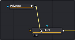
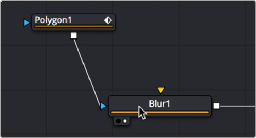
Mask nodes, such as the Polygon, B-Spline, Ellipse, or Rectangle, have a different automatic behavior when you connect them to other nodes. If you drag a connection from a Mask node onto the body of another node, it will automatically connect itself to the default mask input, which is usually the effect mask input. The assumption is that you’re using the mask to limit the node’s effect somehow. However, this isn’t always the case, so you’ll need to be careful of this behavior to make sure you’re attaching your mask to the input that will actually create the effect you need.
Before (left) and after (right) dragging a connection from a Mask node and dropping it on top of a MatteControl node.
Identifying Node Inputs

TIP: Rather than remembering the different knot types, press the right mouse button, hold Option, and drag from the output of a node to the center of another tool. When you release the mouse, a tooltip will appear allowing you to select the knot you want to connect to.
TIP: Rather than remembering the different knot types, press the right mouse button, hold Option, and drag from the output of a node to the center of another tool. When you release the mouse, a tooltip will appear allowing you to select the knot you want to connect to.
TIP: Rather than remembering the different knot types, press the right mouse button, hold Option, and drag from the output of a node to the center of another tool. When you release the mouse, a tooltip will appear allowing you to select the knot you want to connect to.
While you are still figuring out all the nodes and their inputs, hovering the pointer over any knot will display a node tip with the knot’s name.
![]()
Node Order Matters
The order in which nodes are attached defines the order in which each image-processing operation is applied to the image.
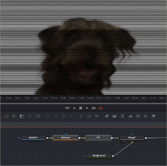
In the following example, a MediaIn node adds a clip to the composition, while a Defocus node blurs the image, and then a TV node adds scanlines and vertical distortion. Those effect nodes are then connected to the MediaOut node in the Fusion page in DaVinci Resolve or a Saver node in Fusion Studio.
![]()
Adding a Defocus effect first, then the TV node second.
As you can see above, connecting the Defocus node first, followed by the TV node, means that while the initial image is softened, the TV effect is sharp. However, if you reverse the order of these two nodes, then the TV effect distorts the image, but the Defocus node now blurs the overall result, so that the TV effect is just as soft as the image it’s applied to. The explicit order of operations you apply makes a big difference.
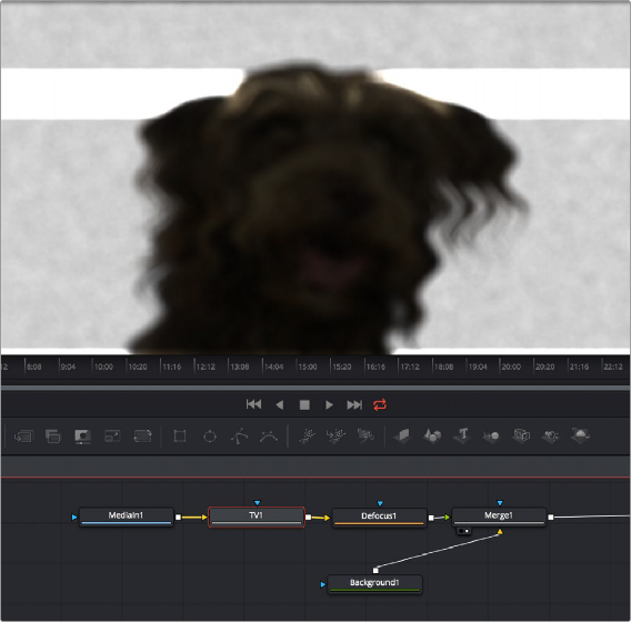
![]()
Adding a TV effect first, and a Defocus second.
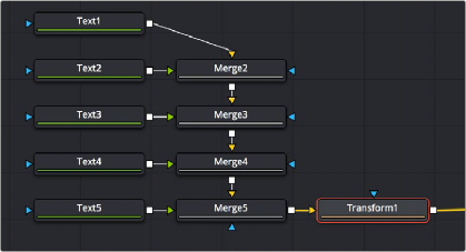
As you can see, the node tree that comprises each composition is a schematic of operations with tremendous flexibility. Additionally, the node tree structure facilitates compositing by giving you the ability to direct each node’s output into separate branches, which can be independently processed and later recombined in many different ways, to create increasingly complex composites while eliminating the need to precompose, nest, or otherwise compound layers together, which would impair the legibility of your composition.
In the following example, several graphics layers are individually transformed and combined with a series of Merge nodes. The result of the last Merge node is then transformed, allowing you to move the entire collection of previous layers around at once. Because each of these operations is clearly represented via the node tree, it’s easy to see everything that’s happening, and why.