< Previous | Contents | Next >
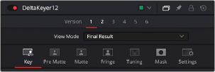
More complicated nodes have more tabs containing more groups of parameters. For example, the Delta Keyer has seven tabs: separating Key, Pre-Matte, Matte, Fringe, Tuning, and Mask parameters, along with the obligatory Settings tab. These tabs keep the Delta Keyer from being a giant scrolling list of settings and make it easy to keep track of which part of the keying process you’re finessing
as you work.
The parameter tabs of the Delta Keyer node
The Settings Tab
![]()
Every node that comes with Fusion has a Settings tab. This tab includes a set of standard controls that appear for nearly every node, although some nodes have special Settings tab controls that others lack.
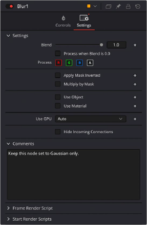
The Settings tab in the Inspector
The following controls are common to most nodes, although some are node-specific. For example, Motion Blur settings have no purpose in a Color Space node.
Blend
The Blend control is found in all nodes, except the Loader, MediaIn, and Generator nodes. It is used to blend between the node’s unaltered image input and the node’s final processed output. When the
blend value is 0.0, the outgoing image is identical to the incoming image. Ordinarily, this will cause the node to skip processing entirely, copying the input straight to the output. The default for this node
is 1.0, meaning the node will output the modified image 100%.
Process When Blend is 0.0
This checkbox forces the node to process even when the input value is zero and the image output is identical to the image input. This can be useful on certain nodes or third-party plugins that store
values from one frame to the next. If this checkbox is disabled on nodes that operate in this manner, the node will skip being processed when the Blend is set to 0, producing incorrect results on subsequent frames.
Red/Green/Blue/Alpha Channel Checkboxes
Most nodes have a set of RGBA boxes in the Settings tab. These selectable boxes let you exclude any combination of these channels from being affected by that node.
![]()
The channel limiting boxes in the Settings panel of a Transform node set so that only the green channel is affected.
![]()
For example, if you wanted to use the Transform node to affect only the green channel of an image, you can turn off the Red, Blue, and Alpha checkboxes. As a result, the green channel is processed by this operation, and the red, blue, and alpha channels are copied straight from the node’s input to the node’s output, skipping that node’s processing to remain unaffected.
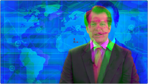
Transforming only the green color channel of the image with a Transform effect
Skipping Channel Processing
Under the hood, most nodes actually process all channels first, but afterward copy the input image to the output for channels that have been unchecked. Modern workstations are so fast that this isn’t usually noticeable, but there are some nodes where deselecting a channel actually causes that node to skip processing that channel entirely. Nodes that operate this way have a linked set of Red, Green, Blue, and Alpha boxes on another tab in the node.
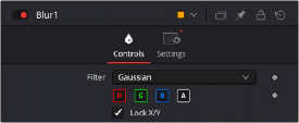
Channel boxes on the Controls tab of the
Blur node indicate that disabled channels won’t be processed at all, to save rendering time..
In these cases, the Common Control channel boxes are instanced to the channel boxes found elsewhere in the node. Blur, Brightness/Contrast, Erode/Dilate, and Filter are examples of nodes that all have RGBY checkboxes in the main Controls tab of the Inspector, in addition to the Settings tab.
Apply Mask Inverted
TIP: The Apply Mask Inverted checkbox option operates only on effects masks, not on garbage masks.
TIP: The Apply Mask Inverted checkbox option operates only on effects masks, not on garbage masks.
TIP: The Apply Mask Inverted checkbox option operates only on effects masks, not on garbage masks.
When the Apply Mask Inverted checkbox is enabled, masks attached to the Effect Mask input of that node are inverted.
Multiply By Mask
Selecting this option will cause the RGB values of the masked image to be multiplied by the Mask channel’s values. This will cause all pixels of the image not included in the mask (i.e., those set to 0) to become black. This creates a premultiplied image.
![]()
Use Object/Use Material (For Masking)
Some 3D animation and rendering software can output to file formats that support auxiliary channels. Notably, the OpenEXR file format supports Object ID and Material ID channels, either of which can be used as a mask for an effect. This checkbox determines whether the channels will be used if they are available. The specific Material ID or Object ID affected is chosen using the next set of controls.
The Sample Controls are only displayed once the Use Object or Use Material checkbox is enabled. These controls select which ID is used to create a mask from the Object or Material channels saved in the image. You use the Sample button to grab IDs from the image in the viewer, the same way you use the Color Picker to select a color, by holding down the left mouse button
on the Sample button, then dragging over to the viewer to the part of the image you want to select. The image or sequence must have been rendered from a 3D software package with those channels included.
The Correct Edges checkbox is only displayed once the Use Object or Use Material checkbox is enabled. When the Correct Edges checkbox is enabled, the Coverage and Background Color channels are used to separate and improve the effect around the edge of the object. When
disabled (or no Coverage or Background Color channels are available), aliasing may occur on the edge of the mask.
Motion Blur
For nodes that are capable of introducing motion, such as Transform nodes, Warp nodes, and so on, the Motion Blur checkbox toggles the rendering of motion blur on or off for that node. When this checkbox is enabled, the node’s predicted motion is used to produce the blur caused by a virtual camera shutter. When the control is disabled, no motion blur is created.
When Motion Blur is disabled, no additional controls are displayed. However, turning on Motion Blur reveals four additional sliders with which you can customize the look of the motion blur you’re adding to that node.
Quality determines the number of samples used to create the blur. The default quality setting of 2 will create two samples on either side of an object’s actual motion. Larger values produce smoother results but will increase the render time.
Shutter Angle controls the angle of the virtual shutter used to produce the Motion Blur effect. Larger angles create more blur but increase the render times. A value of 360 is the equivalent of having the shutter open for one whole frame exposure. Higher values are possible and can be used to create interesting effects. The default value for this slider is 100.
Center Bias modifies the position of the center of the motion blur. Adjusting the value allows for the creation of trail-type effects.
Adjusting Sample Spread modifies the weight given to each sample. This affects the brightness of the samples set with the Quality slider.
![]()
Scripting
Scripting fields are present on every node and contain one or more editable text fields that can be used to add scripts that process when that node is rendering. For more information on the contents of this tab, please consult the Scripting documentation.
Comments
A Comments field is found on every node and contains a single text field that is used to add comments and notes to that node. To enter text, simply click within the field to place a cursor, and begin typing.
When a note is added to a node, the comments icon appears in the Control Header and can be seen in a node’s tooltip when the cursor is placed over the node in the Node Editor. The contents of the Comments tab can be animated over time, if required.
Additional controls appear under this tab if the node is a Loader. For more information, see Chapter 103, “Generator Nodes.” In the DaVinci Resolve Reference Manual or Chapter 41 in the Fusion Reference Manual.