
< Previous | Contents | Next >
Select an aux channel from the color drop-down menu to display the aux channel in the viewer
TIP: The Color Inspector SubView can be used to read numerical values from all of the channels.
TIP: The Color Inspector SubView can be used to read numerical values from all of the channels.
TIP: The Color Inspector SubView can be used to read numerical values from all of the channels.
![]()
Auxiliary Channels Explained
Fusion is capable of using auxiliary channels to perform depth-based compositing, to create masks and mattes based on Object or Material IDs, and for texture replacements. Nodes that work with auxiliary channel information have been specifically developed to work with this data. The auxiliary channels that are supported in Fusion are described below.
Z-Depth
Each pixel in a Z-Depth channel contains a value that represents the relative depth of that pixel in the scene. In the case of overlapping objects in a model, most 3D applications take the depth value from the object closest to the camera when two objects are present within the same pixel since the closest object typically obscures the farther object.
When present, Z-Depth can be used to perform depth merging using the Merge node or to control simulated depth-of-field blurring using the Depth Blur node.
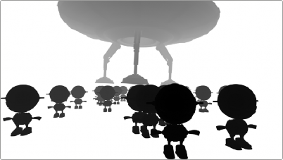
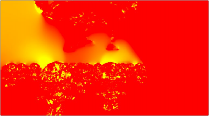
The rendered Z-Depth channel for the previous RGBA image
For this example, we’ll examine the case where the Z-Depth channel is provided as a separate file. The Z- channel can often be rendered as an RGB image. You’ll need to combine the beauty and Z pass using a Channel Booleans node. When the Z pass is rendered as an image in the RGB channels, the Channels Booleans node is used to re-shuffle the Lightness of the foreground RGB channel into the Z-channel.
1 Connect the MediaIn node containing the beauty pass to the background input of the Channel Booleans node.
2 Connect the MediaIn node containing the Z-Depth pass to the green foreground input of the Channel Booleans node.
3 Select the Channel Booleans node, and use the Inspector to set the To Red, To Green, To Blue, and To Alpha menus to Do Nothing.
![]()
4 Select the Aux tab, and set the To Z Buffer menu to Lightness FG.
5 Connect the output of the Channels Booleans node into the Depth Blur node.
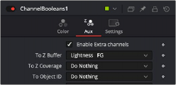
The Aux tab configured to shuffle the Foreground Lightness to the Z-Depth channel.
The Depth Blur node is one of the nodes that take advantage of a Z-channel in order to create blurry depth-of-field simulations. To set this up, the output of the MediaIn node connects to the background input on the Depth Blur.
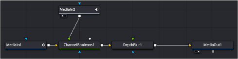
The Depth Blur uses the Z-channel that is enabled in the Channel Booleans node.
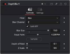
The Depth Blur’s controls in the Inspector are very dependent on the type of image you’re using. It can be easier to begin by adjusting the controls in the Inspector to some better defaults. Start by increasing the Blur Size to 10. This will make it easier to see even the smallest of changes.
Next, instead of using the Focal Point, you should pick a focal point in the image by dragging the Sample button into the viewer and selecting a pixel that determines the part of the picture to keep in focus.
The final setup steps are to lower Z Scale to somewhere around 0.2 (if you’re using a floating- point image), and leave the Depth of Field alone for now. This should show you some blurring in the image.
![]()
Start by improving the defaults if your image is 16- or 32-bit floating point.
Once you see these experimental results, you can return to each parameter and refine it as needed to achieve the actual look you want.
An image using a Z-Depth channel for blurring

TIP: Z-Depth channels often contain negative values. If this causes problems, you can choose Normalize Color Range from the viewer’s Options menu to apply a normalization to the viewer, keeping the image within a range from 0 to 1.
TIP: Z-Depth channels often contain negative values. If this causes problems, you can choose Normalize Color Range from the viewer’s Options menu to apply a normalization to the viewer, keeping the image within a range from 0 to 1.
TIP: Z-Depth channels often contain negative values. If this causes problems, you can choose Normalize Color Range from the viewer’s Options menu to apply a normalization to the viewer, keeping the image within a range from 0 to 1.
Z-Coverage
TIP: The wide adoption of an open-source matte creation technology called Cryptomatte, has somewhat superseded mattes created from Coverage, Background, Object ID, and Material ID passes.
TIP: The wide adoption of an open-source matte creation technology called Cryptomatte, has somewhat superseded mattes created from Coverage, Background, Object ID, and Material ID passes.
TIP: The wide adoption of an open-source matte creation technology called Cryptomatte, has somewhat superseded mattes created from Coverage, Background, Object ID, and Material ID passes.
The Z-Coverage channel is a somewhat extinct render pass in most 3D applications. It was a way of restoring antialiasing to rendered color masks and Z-Depth passes. It indicated pixels in the Z-Depth that contained two objects. The value was used to indicate, as a percentage, how transparent that pixel was in the final depth composite. It can still be used today if you are rendering files from one of the few applications that can produce them.
Background RGBA
This channel is a somewhat extinct render pass in most 3D applications. It contained the color values from the objects behind the pixels described in the Z coverage.
Object ID
Most 3D applications are capable of assigning ID values to objects in a scene. Each pixel in the Object ID channel will be identified by that ID number, allowing for the creation of masks.
![]()
If you want to use an Object ID in a comp, like all aux channels you must map the Object ID pass to the Object ID channel in the MediaIn or Loader Node.
1 In the MediaIn or Loader node, use the Channels or Format tab to map the Object ID pass to the Object ID aux channel.
2 In whatever node you want to have affected by the ObjectID matte, select the Settings tab, turn on the Object ID checkbox, and select the ID number assigned to the object.
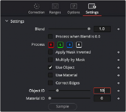
The common Settings tab on most nodes contains ObjectID controls.
Material ID
Most 3D applications are capable of assigning ID values to materials in a scene. Each pixel in the Material ID channel will be identified by that ID number, allowing for masks based on materials.
You can set up Material IDs using the Settings tab, similarly to how ObjectIDs are set.
UV Texture
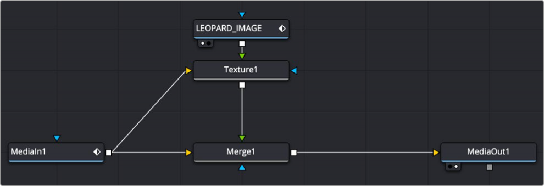
The UV Texture channels contain information about how pixels in an image map to texture coordinates. This is used to retexture an object in a 2D image. For instance, If you want to apply a logo onto a rendered object, you can use the UV aux channel with the Texture node.
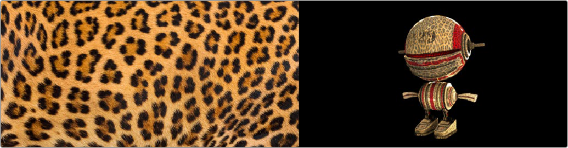
Texture (left) applied to 2D image (right) using UV channels and texture node.
1 In the MediaIn or Loader node, use the Channels or Format tab to map the U and V pass to the U and V aux channels.
2 Connect the output of the MediaIn or Loader node to the background input of the Texture node.
3 Connect the texture image you want to use to the foreground input of the Texture node.
![]()
4 If you want to combine the original texture with the new texture, use a merge with the background input from the original image and the foreground input from the Texture node.
5 Adjust Merge’s Apply mode, Alpha Gain, and blend to get the desired mix of the two textures.

TIP: If you are using a separate UV render pass with the UV data in the RGB channels, map red to U and green to V in a Channel Booleans node.
TIP: If you are using a separate UV render pass with the UV data in the RGB channels, map red to U and green to V in a Channel Booleans node.
TIP: If you are using a separate UV render pass with the UV data in the RGB channels, map red to U and green to V in a Channel Booleans node.
UV channels from a MediaIn node used in a Texture node and merged over the original image
X, Y, and Z Normals
The X, Y, and Z Normal channels contain information about each pixel’s orientation (the direction it faces) in 3D space. The normals are often displayed as lines coming out from your object
perpendicular to the surface, letting you visualize the relationship between the surface and camera.
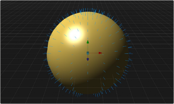
The Normals display the direction of the surface.
The Normals X, Y, and Z channels are often used with a Shader node to perform relighting adjustments on a 2D rendered image.
![]()
1 In the MediaIn or Loader node, use the Channels or Format tab to map the individual X, Y, and Z Normals pass to the X Normal, Y Normal, and Z Normal channels.
2 Connect the output of the MediaIn or Loader node to the background input of the Shader node.
3 Optionally, connect a floating-point EXR image to be used as a reflection image to the Shader node’s reflection input.
4 Adjust the Shader controls to perform relighting.
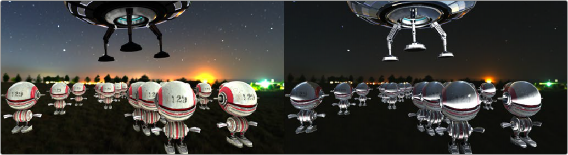
Original 2D image (left) and Normals used for relighting (right)
XY Vector and XY BackVector
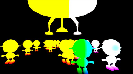
The Vector channels indicates the pixel’s motion from frame to frame. It can be used to apply motion blur to an image or to generate optical flow analysis for retiming. The XY Vector points to the next frame, while the XY BackVector points to the previous frame.
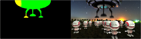
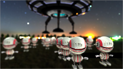
XY Vector pass (left) used with Vector Motion Blur to generate motion blur on spaceship (right)
Often the vector pass will be rendered in a separate pass as an RGB image. The X and Y vector data is located in the R and G channels. In order to place them in the vector channels, you can use a Channel Booleans node.
1 Add a MediaIn or Loader node for the image and the Vector render pass.
2 Connect the output of the image into the background of a Channel Booleans node.
3 Connect the output of the Vector render pass to the Channel Boolean’s foreground
4 In the Channel Booleans inspector, set the To Red, To Green, To Blue, and To Alpha all to Do Nothing.
5 Select to the Aux tab.
![]()
6 Turn on Enable Extra Channels.
7 Set the To X Vector drop-down menu to Red FG, and then set the To Y Vector drop-down menu to Green FG.
8 Connect the Channel Booleans node’s output to the yellow background input on a Vector Motion Blur node.
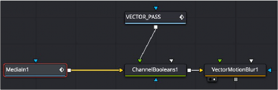
The Vector render pass is combined with the beauty image using the Channels Booleans node, which then feeds the Vector Motion Blur node.
World Position
World Position Pass (WPP) is an auxiliary channel, sometimes referred to as Point Position, XYZ pass, or WPP. It’s used to represent each pixel’s 3D (XYZ) position as an RGB color value. The result is data that can be viewed as a very colorful RGB image. Like Z-Depth, this can be used for
compositing via depth. However, it can also be used for masking based on 3D position, regardless of camera transforms.
The colors correspond to a pixel’s position in 3D, so if a pixel sits at 0/0/0 in a 3D scene, the resulting pixel’s will have an RGB value of 0/0/0 or black. If a pixel sits at 1/0/0 in the 3D scene, the resulting pixel is fully red. Due to the huge extent, 3D scenes can have the WPP channel should always be rendered in 32-bit floating-point to provide the accuracy needed.
XYZ Position
XY Disparity
![]()
XY Disparity is the only channel listed here that is not generated in a 3D application. These channels indicate where each pixel’s corresponding matte can be found in a stereo image. Each eye, left and right, will use this vector to point to where that pixel would be in the other eye. This can be used for adjusting stereo effects, or to mask pixels in stereo space.
Combined X and Y Disparity channels

Using Cryptomatte in Fusion
Cryptomatte is an open-source technology that has been widely adopted in 3D applications. Unlike Z-Depth mattes or Object IDs, Cryptomatte automatically generates anti-aliased
ID mattes from 3D renders with support for motion blur, transparency, and depth of field.
Fusion does not natively support the Cryptomatte format. However, using a free plugin from third-party developers, you can use Crypotmatte render passes in Fusion.
Crypotmatte for Fusion can be downloaded and installed for free: https://github.com/ Psyop/Cryptomatte
Or to use an easier installer, you can download Reactor, which comes bundled with Cryptomatte and offers many other free, useful Fusion plugins. Reactor can be found at: https://www.steakunderwater.com