< Previous | Contents | Next >
Here’s a more detailed explanation of each type of light in Fusion.
Ambient Light
You use ambient light to set a base light level for the scene, since it produces a general uniform illumination of the scene. Ambient light exists everywhere without appearing to come from any particular source; it cannot cast shadows and will tend to fill in shadowed areas of a scene.
Directional Light
A directional light is composed of parallel rays that light up the entire scene from one direction, creating a wall of light. The sun is an excellent example of a directional light source.
Point Light
A point light is a well defined light that has a small clear source, like a light bulb, and shines from that point in all directions.
Spotlight
A spotlight is an advanced point light that produces a well defined cone of light with falloff. This is the only light that produces shadows.
![]()
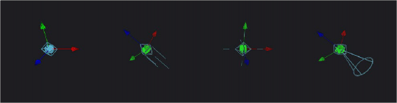
From left to right: Directional light, point light, and spotlight
All of the Light nodes display onscreen controls in the viewer, although not all controls affect every light type. In the case of the ambient light, the position has no effect on the results. The directional light can be rotated, but position and scale will be ignored. The point light ignores rotation. Both position and rotation apply to the spotlight.
Lighting Hierarchies
Lights normally do not pass through a Merge, since the Pass Through Lights checkbox is off by default. This provides a mechanism for controlling which objects are lit by which lights. For example, in the following two node trees, two shapes and an ambient light are combined with a Merge3D node, which is then connected to another Merge3D node that’s also connected to a plane and a spotlight.
At the left, the first Merge3D node of this tree has Pass Through Lights disabled, so you can only see the two shapes lit. At the right, Pass Through Lights has been enabled, so both the foreground shapes and the background image plane receive lighting.
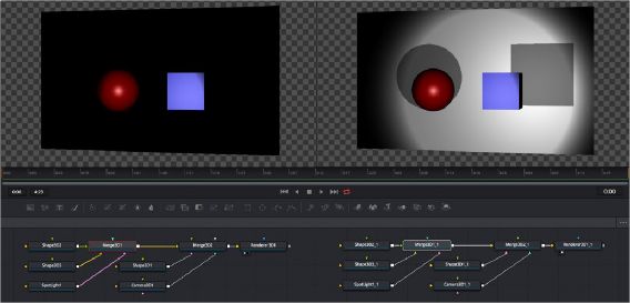
Pass Through Lights is disabled, so only the front two shapes are illuminated (left) Pass Through Lights is enabled, so all shapes connected to both Merge3D nodes are illuminated (right)
Lighting Options
Most nodes that generate geometry have additional options for lighting. These options are used to determine how each individual object reacts to lights and shadows in the scene.
![]()
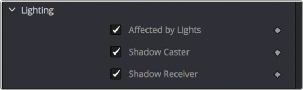
3D objects have individual lighting controls that let you control how each object interacts with light and shadows
— Affected By Lights: If the Affected By Lights checkbox is enabled, lights in the scene will affect the geometry.
— Shadow Caster: When enabled, the object will cast shadows on other objects in the scene.
— Shadow Receiver: If this checkbox is enabled, the object will receive shadows.
Shadows
The only light that can cast shadows is the spotlight. Spotlight nodes cast shadows by default, although these shadows will not be visible in the viewer until shadows are enabled using the viewer toolbar button. Shadows will not appear in the output of the Renderer3D unless the Shadows option is enabled for that renderer. If you want to prevent a spotlight from casting shadows, you can disable the Enable Shadows checkbox in the node’s Inspector.
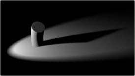
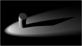
An image with spotlight casting a variable soft shadow
For more information on shadow controls, see the “Spotlight” section of Chapter 90, “3D Light Nodes,” in the DaVinci Resolve Reference Manual or Chapter 30 in the Fusion Reference Manual.
Shadow Maps
A shadow map is an internal depth map that specifies each pixel’s depth in the scene. This information is used to assemble the shadow layer created from a spotlight. All the controls for the shadow map are found in the Spotlight Inspector.
The quality of the shadow produced depends greatly on the size of the shadow map. Larger maps generate better-looking shadows but will take longer to render. The wider the cone of the spotlight, or the more falloff in the cone, the larger the shadow map will need to be to produce useful quality results. Setting the value of the Shadow Map Size control sets the size of the depth map in pixels.
Generally, through trial and error, you’ll find a point of diminishing returns where increasing the size of the shadow map no longer improves the quality of the shadow. It is not recommended to set the size of the shadow maps any larger than they need to be.
![]()
The Shadow Map Proxy control is used to set a percentage by which the shadow map is scaled for fast interactive previews, such as Autoproxy and LoQ renders. A value of .4, for example, represents a 40% proxy.
Shadow Softness
By default, the spotlight generates shadows without soft edges, but there are options for constant and variable soft shadows. Hard-edged shadows will render significantly faster than either of the Soft Shadow options. Shadows without softness will generally appear aliased, unless the shadow map size is large enough. In many cases, softness is used to hide the aliasing rather than increasing the shadow map to preserve memory and avoid exceeding the graphics hardware capabilities.
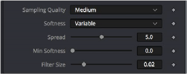
Soft Shadow controls in the Control panel
Setting the spotlight’s shadow softness to None will render crisp and well-defined shadows. The Constant option will generate shadows where the softness is uniform across the shadow, regardless of the shadow’s distance from the casting geometry. The Variable option generates
shadows that become softer as they get farther from the geometry that is casting the shadow.
This is a more realistic effect, but the shadows are somewhat harder to control. When this option is selected, additional controls for adjusting the falloff of the shadow will appear, as well as sliders for the minimum and maximum softness.
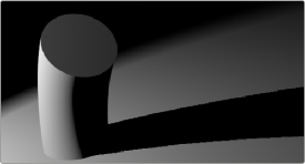
Hard shadow cast by a spotlight
Selecting the Variable option reveals the Spread, Min Softness, and Filter Size sliders. A side
effect of the method used to produce variable softness shadows is that the size of the blur applied to the shadow map can become effectively infinite as the shadow’s distance from the geometry increases. These controls are used to limit the shadow map by clipping the softness calculation to a reasonable limit.
The filter size determines where this limit is applied. Increasing the filter size increases the maximum possible softness of the shadow. Making this smaller can reduce render times but may also limit the softness of the shadow or potentially even clip it. The value is a percentage of the shadow map size.
For more information, see “Spotlight” in Chapter 90, “3D Light Nodes,” in the DaVinci Resolve Reference Manual or Chapter 30 in the Fusion Reference Manual.
Multiplicative and Additive Bias
![]()
Shadows are essentially textures applied to objects in the scene that occasionally result in “fighting.” Z-fighting results when portions of an object that should be receiving shadows instead render over the top of the shadow because they effectively exist in the same exact location in 3D space.
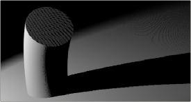
Results of shadow map Z-fighting (top), and the corrected shadow shown using Biasing (bottom)