< Previous | Contents | Next >
Normals are 3 float values (nx, ny, nz) whose components are in the range [–1, +1]. Because you can store only positive values in Fusion’s integer images, the normals are packed from the range [–1, +1] to the range [0, 1] by multiplying by 0.5 and adding 0.5. You can use Brightness Contrast or a Custom node to do the unpacking.
If you were to connect a bump map directly to the bump map input of a material, it will result in incorrect lighting. Fusion prevents you from doing this, however, because Fusion uses a different coordinate system for doing the lighting calculation. You first must use a BumpMap that expects a packed bump map or height map and will do the conversion of the bump map to work correctly.
If your bump mapping doesn’t appear correct, here are a few things to look for:
— Make sure you have the nodes connected correctly. The height/bump map should connect into a BumpMap and then, in turn, should connect into the bump map input on a material.
— Change the precision of the height map to get less banding in the normals. For low frequency images, float32 may be needed.
— Adjust the Height scale on the BumpMap. This scales the overall effect of the bump map.
— Make sure you set the type to HeightMap or BumpMap to match the image input. Fusion cannot detect which type of image you have.
— Check to ensure High Quality is on (right-click in the transport controls bar and choose High Quality from the contextual menu). Some nodes like Text+ produce an anti-aliased version in High Quality mode that will substantially improve bump map quality.
— If you are using an imported normal map image, make sure it is packed [0–1] in RGB and that it is in tangent space. The packing can be done in Fusion, but the conversion to tangent space cannot.
Projection Mapping
![]()
Projection is a technique for texturing objects using a camera or projector node. This can be useful for texturing objects with multiple layers, applying a texture across multiple separate objects, projecting background shots from the camera’s viewpoint, image-based rendering techniques, and much more.
There are three ways to do projection mapping in Fusion.
Using the Projector/Camera Tool to Project Light
When lighting is enabled, a Camera 3D or Projector 3D can act as a light with all the lighting features. When Camera Projection is enabled or you use a projector, you can choose whether the projection behaves like a spotlight or an ambient light; however, alpha channels cannot be projected.
Overlapping projections add together like any other light node. An internal clipping plane (at around 0.01 distance from camera) limits how close the projector or camera can get to the receivers of the projection.
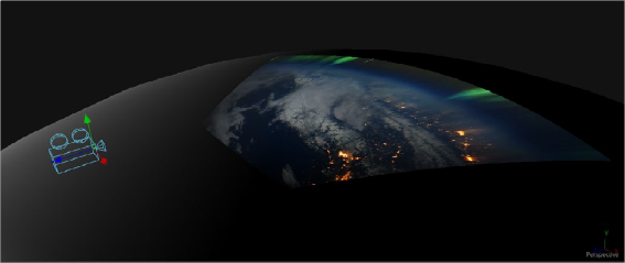
Camera node used for a projection map
Project a Texture onto a Catcher Material
If you do not want to work with light sources, you can use the projector or camera as a texture projector. To work without lighting, a catcher is required in order to receive the texture and apply it to a material. Only objects using this material will receive the projection. This offers some advantages, like the projection of alpha channels, and texturing other channels like specular color or roughness. If the software renderer is used, overlapping projections can be combined in various ways (mean, median, blend, and so on) via the Catcher node. When using the OpenGL renderer, one catcher
![]()
per projector is used, and the results can be combined using another material. Similar to the Light Projection technique, an internal clipping plane (at around 0.01 distance from camera) limits how close the projector/camera can get to the projection receivers.
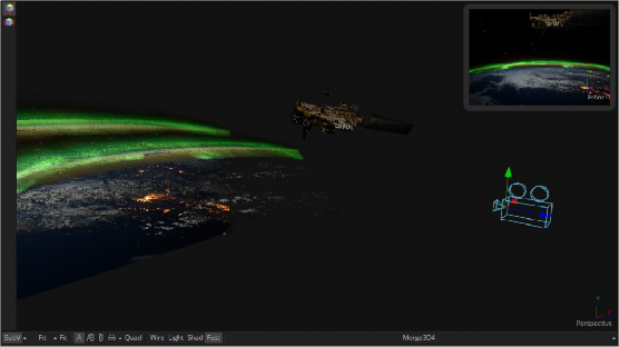
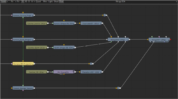
Camera projection used with a Catcher node (example from an older version of Fusion)
Project Using the UVMap Node
This mode requires a camera and a UVMap3D node downstream of the objects to which the texture is being projected. In the Inspector, when the UVMap Map mode is set to Camera, it gathers the information from the camera and creates new UVs for the input objects, which are used for texturing. Because the UVs are stored in the vertices of the mesh, the object must be tessellated sufficiently.

TIP: Projected textures can be allowed to slide across an object. If the object moves relative to the Projector 3D, or alternatively, by grouping the two together with a Merge3D, they can be moved as one and the texture will remain locked to the object.
TIP: Projected textures can be allowed to slide across an object. If the object moves relative to the Projector 3D, or alternatively, by grouping the two together with a Merge3D, they can be moved as one and the texture will remain locked to the object.
TIP: Projected textures can be allowed to slide across an object. If the object moves relative to the Projector 3D, or alternatively, by grouping the two together with a Merge3D, they can be moved as one and the texture will remain locked to the object.
![]()
Textures are assigned to the object like any other texturing technique. The UVs can be locked to the vertices at a chosen frame using the Ref Time slider. This locking only works as long as vertices are not created, destroyed, or reordered (e.g., projection locking will not work on particles because they get created/destroyed, nor will they work on a Cube3D when its subdivision level slider is animated).
In the following section of a much larger composition, an image (the Loader1 node) is projected into 3D space by mapping it onto five planes (Shape3D nodes renamed ground, LeftWall, RightWall, Building, and Background), which are positioned as necessary within a Merge3D node to apply reflections onto a 3D car to be composited into that scene.
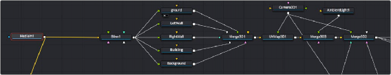
Excerpt of a composition that’s projecting an image of a street scene into 3D space