
< Previous | Contents | Next >
DisparityToZ, ZToDisparity
TIP: If the colors between shots are different, use Color Corrector or Color Curves to do a global alignment first before calculating the Disparity map. Feed the image you will change into the orange input and the reference into the green input. In the Histogram section of the Color Corrector, select Match, and also select Snapshot Match Time. In the Color Curves’ Reference section, select Match Reference.
TIP: If the colors between shots are different, use Color Corrector or Color Curves to do a global alignment first before calculating the Disparity map. Feed the image you will change into the orange input and the reference into the green input. In the Histogram section of the Color Corrector, select Match, and also select Snapshot Match Time. In the Color Curves’ Reference section, select Match Reference.
TIP: If the colors between shots are different, use Color Corrector or Color Curves to do a global alignment first before calculating the Disparity map. Feed the image you will change into the orange input and the reference into the green input. In the Histogram section of the Color Corrector, select Match, and also select Snapshot Match Time. In the Color Curves’ Reference section, select Match Reference.
These nodes pass through, modify, or generate new aux channels, but do not destroy any.
Separate vs. Stack
Stereo nodes can work in Separate or Stack modes. When in Stack mode, the left/right eyes are stacked horizontally or vertically, forming one image with double width or height, respectively.
The advantage to using Stack mode is that you do not have to have duplicate branches of the Node Editor for the left and right eyes. As a consequence, you will see Stereo nodes with two inputs and two outputs labeled as “Left” and “Right.”
When in Stack mode, the stack should be connected to the left eye input and the Left output should be used for connecting further nodes. In Stack mode, the respective Right eye inputs and outputs are hidden.
Setting Up Stereo in the Node Editor
![]()
The disparity generation is the first operation. This can be configured in the Node Editor in two different ways.
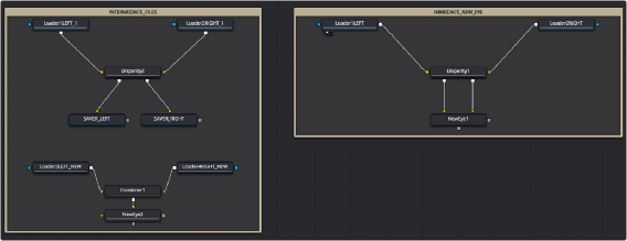
Two stereoscopic workflows.
In the above example, the workflow on the right takes the left and right eye, generates the disparity, and then NewEye is used to generate a new eye for the image right away.
The example on the left renders the frames with disparity to intermediate EXR images. These images are then loaded back into Stereo nodes and used to create the NewEye images.