< Previous | Contents | Next >
The function of the controls found in the Controls tab is straightforward. First, you select the option to override using the Do [Option] checkbox. That reveals a control that can be used to set the value of the option itself. The individual options are not documented here; a full description of each can be found in any geometry creation node in this chapter, such as the Image Plane, Cube, or Shape nodes.
Enables the override for this option.
If the Do [Option] checkbox is enabled, then the control for the property itself becomes visible. The control values of the properties for all upstream objects are overridden by the new value.
Common Controls
The Settings tab includes controls common to most 3D nodes. Their descriptions can be found in “The Common Controls” section at the end of this chapter.
Point Cloud 3D [3PC]
![]()
The PointCloud 3D node
Point Cloud 3D Node Introduction
A Point Cloud is generally many null objects created by 3D tracking or modeling software.
NOTE: A null object is an invisible 3D object that has all the same transform properties of a visible 3D object.
NOTE: A null object is an invisible 3D object that has all the same transform properties of a visible 3D object.
NOTE: A null object is an invisible 3D object that has all the same transform properties of a visible 3D object.
When produced by 3D tracking software, the points typically represent each of the patterns tracked to create the 3D camera path. These point clouds can be used to identify a ground plane and to orient other 3D elements with the tracked image. The Point Cloud 3D node creates a point cloud either by importing a file from a 3D tracking application or generating it when you use the Camera Tracker node.
Inputs
The Point Cloud has only a single input for a 3D scene.
— SceneInput: This orange input accepts a 3D scene.
Basic Node Setup
The Point Cloud 3D node is viewed and connected through a Merge 3D node, integrating it into the larger 3D scene.
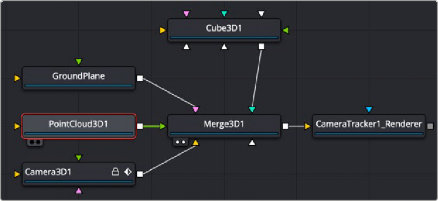
Point Cloud 3D connected and viewed through a Merge 3D
![]()
Inspector
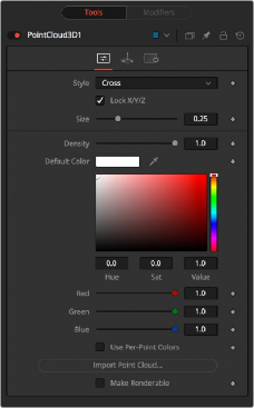
Point Cloud 3D controls
Controls Tab
The Controls tab is where you can import the point cloud from a file and controls its appearance in the viewer.
The Style menu allows you to display the point cloud as cross hairs or points in the viewer.
Deselect this checkbox to provide individual control over the size of the X, Y, and Z arms of the points in the cloud.
These sliders can be used to increase the size of the onscreen crosshairs used to represent each point.
This slider defines the probability of displaying a specific point. If the value is 1, then all points are displayed. A value of 0.2 shows only every fifth point.
Use the standard Color control to set the color of onscreen crosshair controls.
The Import Point Cloud button displays a dialog to import a point cloud from another application. Supported file types are:
Alias's Maya | .ma |
3DS Max ASCII Scene Export | .ase |
NewTek's LightWave | .lws |
Softimage XSI's | .xsi. |
![]()
Determines whether the point cloud is visible in the OpenGL viewer and in final renderings made by the OpenGL renderer. The software renderer does not currently support rendering of visible crosshairs for this node.
This checkbox control appears when the Make Renderable option is selected. If the Unseen by Cameras checkbox is selected, the point cloud is visible in the viewers but not rendered into the output image by the Renderer 3D node.
Common Controls
The remaining Transform and Settings tabs are common to many 3D nodes. Their descriptions can be found in “The Common Controls” section at the end of this chapter.
Onscreen Contextual Menu
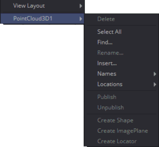
The Point Cloud 3D contextual menu options
Frequently, one or more of the points in an imported point cloud is manually assigned to track the position of a specific feature. These points usually have names that distinguish them from the rest of the points in the cloud. To see the current name for a point, hover the mouse pointer directly over a point, and after a moment a small tooltip appears with the name of the point.
When the Point Cloud 3D node is selected, a submenu is added to the viewer’s contextual menu with several options that make it simple to locate, rename, and separate these points from the rest of the point cloud.
![]()
The contextual menu contains the following options:
— Find: Selecting this option from the viewer contextual menu opens a dialog to search for and select a point by name. Each point that matches the pattern is selected.
— Rename: Rename any point by selecting Rename from the contextual menu. Type the new name into the dialog that appears and press Return. The point now has that name, with a four-digit number added to the end. For example, the Name window is window0000, and multiple points would be window0000, window0001, and so on. Names must be valid Fusion identifiers (i.e., no spaces allowed, and the name cannot start with a number).
— Delete: Selecting this option deletes the currently selected points.
— Publish: Normally, the exact position of a point in the cloud is not exposed. To expose the position, select the points, and then select the Publish option from this contextual menu. This adds a coordinate control to the control panel for each published point that displays the point’s current location.