
< Previous | Contents | Next >
Fusion does exactly the same thing as 3D applications when you make a surface two sided.
NOTE: This can become rather confusing once you make the surface transparent, as the same rules still apply and produce a result that is counterintuitive. If you view from the frontside a transparent two-sided surface illuminated from the backside, it looks unlit.
NOTE: This can become rather confusing once you make the surface transparent, as the same rules still apply and produce a result that is counterintuitive. If you view from the frontside a transparent two-sided surface illuminated from the backside, it looks unlit.
NOTE: This can become rather confusing once you make the surface transparent, as the same rules still apply and produce a result that is counterintuitive. If you view from the frontside a transparent two-sided surface illuminated from the backside, it looks unlit.
The confusion about what two-sided lighting does arises because Fusion does not cull back-facing polygons by default. If you revolve around a one-sided plane in Fusion, you still see it from the backside (but you are seeing the frontside duplicated through to the backside as if it were transparent). Making the plane two sided effectively adds a second set of normals to the backside of the plane.
This slider sets the numeric identifier assigned to this material. This value is rendered into the MatID auxiliary channel if the corresponding option is enabled in the renderer.
Common Controls
The Settings tab in the Inspector is duplicated in other 3D nodes. These common controls are described in detail at the end of this chapter in “The Common Controls” section.
Channel Boolean [3Bol]
![]()
The Channel Boolean node
Channel Boolean Node Introduction
The Channel Boolean (not to be confused with the 2D Channel Booleans) can be used to remap and modify channels of 3D materials using mathematical operations. For example, if you want to use the red channel of a material to control a scalar input of an illumination model that uses the Alpha channel (e.g., Blinn. SpecularExponent), you can remap the channels here. Furthermore, it allows the use of geometry-specific information like texture space coordinates and normals.
Inputs
There are two inputs on the Channel Boolean Node: one for the foreground material, and one for the background material. Both inputs accept either a 2D image or a 3D material like Blinn, Cook-Torrence, or Phong node.
— BackgroundMaterial: The orange background material input accepts a 2D image or a 3D material.
— ForegroundMaterial: The green foreground input also accepts a 2D image or a 3D material.
Basic Node Setup
There are many uses for the material 3D Channel Boolean. Most often it is used to combine material looks or manipulate UV texture coordinates
In the below example, the Channel Boolean node combines the Cook Torrance and Blinn materials. It uses the math operands in the Channel Boolean to switch, invert, and mix the two inputs, creating a neon flickering effect.
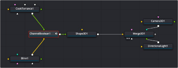
A Channel Boolean used to combine and operate on Cook Torrance and Blinn nodes
![]()
Inspector
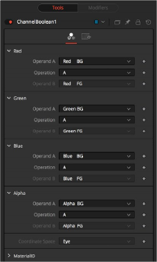
Channel Boolean controls
Controls Tab
The Controls tab includes a section for each RGBA channel. Within each channel are two input menus called Operand A and Operand B. The function performed on these two inputs is selected in the Operation menu.
The Operand menus, one for each output RGBA channel, allow you to set the desired input information for the corresponding channel.
— Red/Green/Blue/Alpha FG
Reads the color information of the foreground material.
— Red/Green/Blue/Alpha BG
Reads the color information of the background material.
— Black/White/Mid Gray
Sets the value of the channel to 0, 0.5, or 1.
— Hue/Lightness/Saturation FG
Reads the color information of the foreground material, converts it into the HLS color space, and puts the selected information into the corresponding channel.
— Hue/Lightness/Saturation BG
Reads the color information of the background material, converts it into the HLS color space, and puts the selected information into the corresponding channel.
— Luminance FG
Reads the color information of the foreground material and calculates the luminance value for the channel.
![]()
— Luminance BG
Reads the color information of the background material and calculates the luminance value for the channel.
— X/Y/Z Position FG
Sets the value of the channel to the position of the pixel in 3D space. The vector information is returned in eye space.
— U/V/W Texture FG
Applies the texture space coordinates of the foreground material to the channels.
— U/V/W EnvCoords FG
Applies the environment texture space coordinates to the channels. Use it upstream of nodes modifying the environment texture coordinates like the Reflect 3D node.
— X/Y/Z Normal
Sets the value of the channel to the selected axis of the normal vector. The vector is returned in eye space.