< Previous | Contents | Next >
The ranges are selected by manipulating the spline handles. There are four spline points, each with one Bézier handle. The two handles at the top represent the start of the shadow and highlight ranges, whereas the two at the bottom represent the end of the range. The Bézier handles are used to control the falloff.
The midtones range has no specific controls since its range is understood to be the space between the shadow and the highlight ranges. The X and Y text controls below the Spline display can be used to enter precise positions for the selected Bézier point or handle.
These two buttons can be used to return the spline ranges to either Smooth (default) or Simple (linear) settings.
Settings Tab
The Settings tab in the Inspector is also duplicated in other Color nodes. These common controls are described in detail at the end of this chapter in “The Common Controls” section.
Color Matrix [CMx]
The Color Matrix node
![]()
Color Matrix Node Introduction
The ColorMatrix allows a vast number of operations to modify values individually in the different color channels.
Inputs
The Color Matrix node includes two inputs: one for the main image and the other for an effect mask.
— Input: This orange input is the only required connection. It connects a 2D image that is adjusted by the color matrix.
— Effect Mask: The optional blue effect mask input accepts a mask shape created by polylines, basic primitive shapes, paint strokes, or bitmaps from other tools. Connecting a mask to this input limits the color matrix adjustment to only those pixels within the mask. An effect mask is applied to the tool after it is processed.
Basic Node Setup
The Color Matrix node, like many 2D image-processing nodes, receives a 2D image like a Loader node or the MediaIn1 shown below. The output continues the node tree by connecting to another 2D image-processing node or a Merge node.
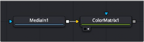
A Color Matrix node applied to a MediaIn1 node
Inspector
Color Matrix controls
![]()
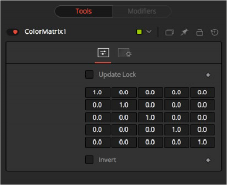
Controls Tab
Color Matrix multiplies the RGBA channels based on the values entered in a 4 x 4 grid. The fifth column/row is an Add column.
When this control is selected, Fusion does not render the node. This is useful for setting up each value of the node, and then turning off Update Lock to render it.
This defines what type of operation actually takes place. The horizontal rows define the output values of the node. From left to right, they are R, G, B, A, and Add. The vertical columns define the input values. From top to bottom, they are R, G, B, A, and Add. The Add column allows simple adding of values to the individual color channels.
By default, the output values are identical to the input values.
— 1.0 means 100% of the Red channel input is copied to the Red channel output.
— 1.0 means 100% of the Green channel input is copied to the Green channel output.
— 1.0 means 100% of the Blue channel input is copied to the Blue channel output.
— 1.0 means 100% of the Alpha channel input is copied to the Alpha channel output.
Written as mathematical equations, the default settings of the matrix would appear as follows:
[R | out] | = | 1 | * [R | in] | + | 0 | * [G | in] | + | 0 | * [B | in] | + | 0 | * [A | in] | + | 0 |
[G | out] | = | 0 | * [R | in] | + | 1 | * [G | in] | + | 0 | * [B | in] | + | 0 | * [A | in] | + | 0 |
[B | out] | = | 0 | * [R | in] | + | 0 | * [G | in] | + | 1 | * [B | in] | + | 0 | * [A | in] | + | 0 |
[A | out] | = | 0 | * [R | in] | + | 0 | * [G | in] | + | 0 | * [B | in] | + | 1 | * [A | in] | + | 0 |
Enabling this option inverts the Matrix. Think of swapping channels around, doing other operations with different nodes, and then copying and pasting the original ColorMatrix and setting it to Invert to get your channels back to the original.
Example 1: Invert
If you want to do a simple invert or negative of the color values, but leave the Alpha channel untouched, the matrix would look like this:
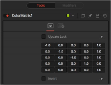
Color Matrix example
![]()
Observe the fact that we have to add 1 to each channel to push the inverted values back into the positive numbers.
Let’s follow this example step by step by viewing the waveform of a 32-bit grayscale gradient.
1 The original grayscale.
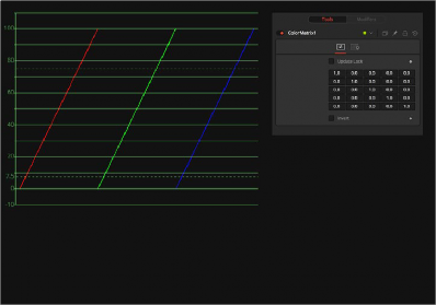
Original Grayscale
2 RGB set to -1. The values get inverted but fall below 0.
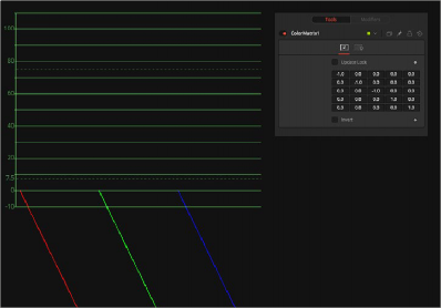
RGB set to -1
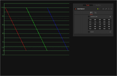
3 Adding 1 to each channel keeps the inversion but moves the values back into a positive range.
![]()
Adding 1 to each channel
Example 2: Brightness per Channel
This example influences the brightness of each channel individually. This subtracts 0.2 from the red channel, adds 0.314 to the green channel, and adds 0.75 to the blue channel, while keeping Alpha as it is.
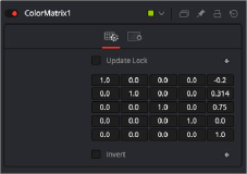
Brightness per channel example