< Previous | Contents | Next >
When remapping is enabled, the currently selected aux channel is rescaled, linearly mapping the range according to the From and To slider selections as explained below. The Remapping options are applied before the conversion operation. This means you could set the From > Min-Max values to -1, 1 to rescale your normals into the [0, 1] range, or set them to [-1000, 0] to rescale your Z values from [-1000, 0] into the [0, 1] range before the clipping occurs.
Note that the Remapping options are per channel options. That means the default scale for normals can be set to [-1, +1] > [0, 1] and for Z it can be set [-1000, 0] > [0, 1]. When you flip between normals and Z, both options are remembered. One way this could be useful is that you can set up the remapping ranges and save this as a setting that you can reuse. The remapping can be useful to squash the aux channels into a static [0, 1] range for viewing or, for example, if you wish to compress normals into the [0, 1] range to store them in an int8 image.
— From > Min: This is the value of the aux channel that corresponds to To > Min.
— From > Max: This is the value of the aux channel that corresponds to To > Max. It is possible to set the max value less than the min value to achieve a flip/inversion of the values.
— Detect Range: This scans the current image to detect the min/max values and then sets the From > Min/ From > Max Value controls to these values.
— Update Range: This scans the current image to detect the min/max values and then enlarges the current [From > Min, From > Max] region so that it contains the min/max values from the scan.
— To > Min: This is the minimum output value, which defaults to 0.
— To > Max: This is the maximum output value, which defaults to 1.
— Invert: After the values have been rescaled into the [To > Min, To > Max] range, this inverts/flips the range.
Settings Tab
![]()
The Settings tab in the Inspector is also duplicated in other Color nodes. These common controls are described in detail at the end of this chapter in “The Common Controls” section.
Gamut [Gmt]
The Gamut node
Gamut Node Introduction
The Gamut node has controls to transform one color space to another and remove/add gamma curves. This node, along with the Cineon Log node, is primarily used to linearize incoming images and then reapply the applicable output gamma curve at the end of a node tree.
Inputs
The Gamut node includes two inputs: one for the main image and the other for an effect mask to limit the conversion area.
— Input: This orange input is the only required connection. It connects a 2D image output that is the source of the gamut conversion.
— Effect Mask: The optional blue effect mask input accepts a mask shape created by polylines, basic primitive shapes, paint strokes, or bitmaps from other tools. Connecting a mask to this input limits the Gamut operation to only those pixels within the mask. An effect mask is applied to the tool after the tool is processed.
Basic Node Setup
A Gamut node is most often placed directly after the MediaIn node in DaVinci Resolve or a Loader node in Fusion Studio. Another Gamut node is usually placed at the end of a node tree before a MediaOut node in DaVinci Resolve or a Saver node in Fusion Studio.
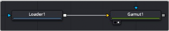
A Gamut node applied to a MediaIn1 node
![]()
Inspector
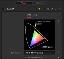
Gamut controls
Controls Tab
The Controls tab is where all the conversion operations take place. It has a section for incoming images and a section for the node’s output. Which section you use depends on whether you are stripping an image of a gamma curve to make it linear or converting a linear image to a specific color space and gamma curve for output.
Source Space determines the input color space of the image. When placed directly after a Loader node in Fusion or a MediaIn node in DaVinci Resolve, you would select the applicable color space based on how the image was created and check the Remove Gamma checkbox. The output of the node would be a linearized image. You leave this setting at No Change when you are adding gamma using the Output Space control and placing the node directly before the Saver node in Fusion or a MediaOut node in DaVinci Resolve.
The DCI-P3 color space is most commonly used in association with DLP projectors. It is frequently provided as a color space available with DLP projectors and as an emulation mode for 10-bit LCD monitors such as the HP Dreamcolor and Apple’s Pro Display XDR. This color space is defined in the SMPTE-431-2 standard.
![]()
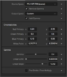
The Custom gamut allows you to describe the color space according to CIE 1931 primaries and white point, which are expressed as XY coordinates, as well as by gamma, limit, and slope. For example, the DCI-P3 gamut mentioned above would have the following values if described as a Custom color space.
Red Primary | 0.68 | 0.32 |
Green Primary | 0.265 | 0.69 |
Blue Primary | 0.15 | 0.06 |
White Point | 0.314 | 0.351 |
Gamma | 2.6 | – |
Linear Limit | 0.0313 | – |
To understand how these controls work, you could view the node attached to a gradient background in Waveform mode and observe how different adjustments modify the output.

NOTE: When outputting to HD specification Rec. 709, Fusion uses the term Scene to refer to a gamma of 2.4 and the term Display for a gamma of 2.2.
NOTE: When outputting to HD specification Rec. 709, Fusion uses the term Scene to refer to a gamma of 2.4 and the term Display for a gamma of 2.2.
NOTE: When outputting to HD specification Rec. 709, Fusion uses the term Scene to refer to a gamma of 2.4 and the term Display for a gamma of 2.2.
Output Space converts the gamut to the desired color space. For instance, when working with linearized images in a composite, you place the Gamut node just before the Saver node and use the Output Space to convert to the gamut of your final output file. You leave this setting at No Change when you want to remove gamma using the Source Space control.