< Previous | Contents | Next >
Alpha Gain linearly scales the Alpha channel values of the trailing objects in front. This effectively reduces the amount that the trailing objects in the background are obscured, thus brightening the overall result. When the Subtractive/Additive slider is set to Additive with Alpha Gain set to 0.0, the foreground pixels are added to the background.
When the Subtractive/Additive slider is set to Subtractive, this controls the density of the composite, similar to Blend.
The Burn In control adjusts the amount of Alpha used to darken the objects that trail under other objects, without affecting the amount of foreground objects added. At 0.0, the blending behaves like a straight Alpha blend. At 1.0, the objects in the front are effectively added onto the objects in the back (after Alpha multiplication if in Subtractive mode). This gives the effect of the foreground objects brightening the objects in the back, as with Alpha Gain. In fact, for Additive blends, increasing the Burn In gives an identical result to decreasing Alpha Gain.
When enabled, the current image is placed under the generated trail, rather than the usual, over top operation. The layer order of the trailing elements is also reversed, making the last trail the topmost layer.
Common Controls
The Settings tab controls are common to all Effect nodes, so their descriptions can be found in “The Common Controls” section at the end of this chapter.
![]()
TV [TV]
The TV node
TV Node Introduction
The TV node is a simple node designed to mimic some of the typical flaws seen in analog television broadcasts and screens. This Fusion-specific node is mostly obsolete when using DaVinci Resolve because of the more advanced Analog Damage ResolveFX.
Input
The two inputs on the TV node are used to connect a 2D image and an effect mask, which can be used to limit the area where the TV effect appears.
— Input: The orange input is used for the primary 2D image that gets the TV distortion applied.
— Effect Mask: The blue input is for a mask shape created by polylines, basic primitive shapes, paint strokes, or bitmaps from other tools. Connecting a mask to this input limits the area where the TV effect to appears. An effects mask is applied to the tool after the tool is processed.
Basic Node Setup
The output of an image is connected to the input of the TV node. The style of TV interference is then customized using the controls in the Inspector.
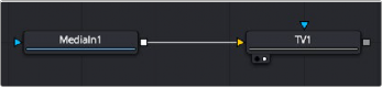
The TV node simulates TV-style flaws in the image connected to the orange input
![]()
Inspector
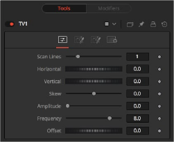
TV node controls
Controls Tab
The Controls tab is the first of three tabs used to customize the analog TV distortion. The Controls tab modifies the scan lines and image distortion of the effect.
This slider is used to emulate the interlaced look by dropping lines out of the image. Setting it to black, with a transparent Alpha, drops a line. A value of 1 (default) drops every second line. A value of 2 shows one line, and then drops the second and third and repeats. A value of zero turns off the effect.
Use this slider to apply a simple Horizontal offset to the image.
Use this slider to apply a simple Vertical offset to the image.
This slider is used to apply a diagonal offset to the image. Positive values skew the image to the top left. Negative values skew the image to the top right. Pixels pushed off frame wrap around and reappear on the other side of the image.
The Amplitude slider can be used to introduce smooth sine wave-type deformation to the edges of the image. Higher values increase the intensity of the deformation. Use the Frequency control to determine how often the distortion is repeated.
The Frequency slider sets the frequency of the sine wave used to produce distortion along the edges of the image when the amplitude control is greater than 1.
Use Offset to adjust the position of the sine wave, causing the deformation applied to the image via the Amplitude and Frequency controls to see across the image.
Noise Tab
![]()
The Noise tab is the second of three tabs used to customize the analog TV distortion. The Noise tab modifies the noise in the image to simulate a weak analog antenna signal.
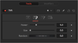
The TV Noise tab
Increase the value of this slider above 0 to introduce noise into the image. The higher the value, the stronger the noise.
Use this slider to scale the noise map larger.
If this thumbwheel control is set to 0, the noise map is static. Change the value over time to cause the static to change from frame to frame.
Roll Bar Tab
The Roll Bar tab is the third of three tabs used to customize the analog TV distortion. The Roll Bar tab animates the bar.
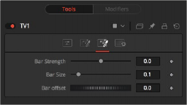
The TV Roll Bar tab
At the default value of 0, no bar is drawn. The higher the value, the darker the area covered by the bar becomes.
Increase the value of this slider to make the bar taller.
Animate this control to scroll the bar across the screen.
Common Controls
![]()
The Settings tab controls are common to all Effect nodes, so their descriptions can be found in the following “The Common Controls” section.