< Previous | Contents | Next >
The Saver node

NOTE: The Saver node in DaVinci Resolve is only used for exporting EXR files.
NOTE: The Saver node in DaVinci Resolve is only used for exporting EXR files.
NOTE: The Saver node in DaVinci Resolve is only used for exporting EXR files.
Saver Node Introduction
The Saver node represents the final composition output from Fusion Studio. It is used to render out movie files or sequential images but can be inserted into a composition at any point to render out intermediate stages of a composition. A composition can contain any number of Saver nodes for rendering different branches of a comp as well as different formats.
The Saver node can also be used to add scratch track audio to your composition, which can be heard during interactive playback.
Inputs
The single input on the Saver node is for the final composition you want to render.
![]()
— Image Input: The orange input is used to connect the resulting image you want rendered.
Basic Node Setup
The Saver node is placed at the end of the composition. Multiple Savers can be placed in a comp to render different formats or to render different parts of a composition.
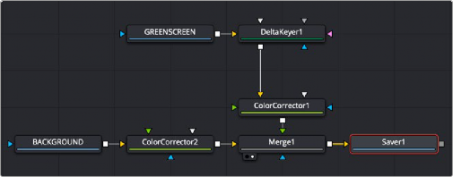
Saver node added to the end of a node tree to render the composition
Inspector
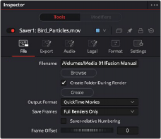
Saver File tab
File Tab
The Saver File tab is used to set the location and output format for the rendered file.
The Filename dialog is used to select the name and path of the rendered image output. Click on the Browse button to open a file browser and select a location for the output.
Sequence numbering is automatically added to the filename when rendering a sequential image file format. For example, if c\renders\image.exr is entered as the filename and 30 frames of output are rendered, the files are automatically numbered as image0000.tga, image0001.exr, image0003.exr... and so on. Four-digit padding is automatically used for numbers lower than 10000.
You can specify the number of digits to use for padding by explicitly entering the digits into the filename.
![]()
For example, image000000.exr would apply 6-digit padding to the numeric sequence, image.001.exr would use 3-digit padding, and image1.exr would use none.
This menu is used to select the image format to be saved. Be aware that selecting a new format from this menu does not change the extension used in the filename to match. Modify the filename manually to match the expected extension for that format to avoid a mismatch between name and image format.
This control selects between two modes of rendering: Full Renders Only or High Quality Interactive.
— Full Renders Only: This is the common setting for most situations. Images are saved to disk when a final render is started using the Start Render button in the Time Ruler.
— High Quality Interactive: This render mode is designed for real-time rendering when painting and rotoscoping. Fusion saves each frame to disk as it is processed interactively. When used correctly, this feature can eliminate the need to perform a final render after rotoscoping.

NOTE: The High Quality Interactive setting can easily cause confusion when used in conjunction with a node tree that contains spline-animated parameters. If these splines are modified in such a way that frames already saved interactively are changed, the frames
already on the disk do not automatically re-render. Either step through each frame again or perform a final render to make certain that the result is correct
This thumbwheel control can be used to set an explicit start frame for the number sequence applied to the rendered filenames. For example, if Global Start is set to 1 and frames 1-30 are rendered, files are normally numbered 0001-0030. If the Sequence Start Frame is set to 100, the rendered output would be numbered from 100-131.
Saver Export tab
![]()
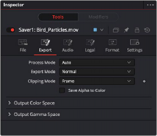
Export Tab
Use this menu to select the Fields Processing mode used by Fusion when saving the images or movie file to disk. The Has Fields checkbox control in the Frame Format preferences determines the default option, and the default height as well. Available options include:
— Full frames
— NTSC fields
— PAL/HD fields
— PAL/HD fields (reversed)
— NTSC fields (reversed).
The two reversed options save fields in the opposite order and thus result in the fields being spatially swapped both in time order and in vertical order as well.
This menu is used to render out the file normally or apply a SMPTE standard 3:2 pulldown to the footage, converting the footage from 24 fps to 30 fps.
This menu, sometimes considered source image clipping, defines how the edges of the image should be treated.
— Frame: The default Frame setting clips to the parts of the image visible within its visible dimensions. It breaks any infinite-workspace behavior. If the upstream DoD is smaller than the frame, the remaining area in the frame is treated as black/transparent.
— None: This setting does not perform any source image clipping at all. This means that any data that would normally be needed outside the upstream DoD is treated as black/transparent.
Be aware that this might create humongous images that can consume a considerate amount of disk space. So you should use this option only if really needed.
For more information about ROI, DoD, and Infinite Workspace, see Chapter 69, “Using Viewers.” in the DaVinci Resolve Reference Manual, or Chapter 7 in the Fusion Reference Manual.
When enabled, this control causes the Alpha channel to be saved into the color channels as a grayscale image. This completely overwrites any existing color information.
This menu is used to set the Color Space of the output file so you could, for example, color space convert images from linear to Rec709, etc., thereby delivering linear EXRs, 709 Quicktimes, etc. from a single source. The images are not being converted in the Comp, only in the images saved to
disk are converted.
— Auto: Passes along any metadata that might be in the rendered image.
— Space: Allows the user to set the color space based on the output format.
![]()
This menu is used to select a Gamma curve of the rendered file. Once the gamma curve type is set, you can choose to apply the curve for output.
— Auto: Passes along any metadata that might be in the incoming image.
— Space: Allows the user to set the gamma curve based on the selected file format.
— Log: Displays the Log/Lin settings, similar to the Cineon Log node. For more detail on the Log settings, see Chapter 98, “Film Nodes.” in the DaVinci Resolve Reference Manual, or Chapter 36 in the Fusion Reference Manual.
Depending on the selected Curve Type or on the Gamma Space found in Auto mode, the associated Gamma Curve is applied, effectively converting from a linear working space.
Audio Tab
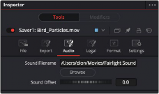
Saver Audio tab

NOTE: This tab is only available in Fusion Studio’s Saver node.
NOTE: This tab is only available in Fusion Studio’s Saver node.
NOTE: This tab is only available in Fusion Studio’s Saver node.
The audio functionality is included in Fusion Studio for scratch track (aligning effects to audio and clip timing) purposes only. Final renders should almost always be performed without audio. The smallest possible audio files should be used, as Fusion loads the entire audio file into memory for efficient display of the waveform in the Timeline. The audio track is included in the saved image if a Quicktime file format is selected. Fusion currently supports playback of WAV audio.
You can enter the file path and name of the audio clip you want to use in the Source Filename field. You can also click the Browse button to open a file browser window and locate the audio scratch track. Select the WAV file of choice, and then in the keyframes panel expand the Saver bar to view the audio waveform. Drag the pointer over the audio wave in the Timeline layout to hear the track.
![]()
Drag the control left or right to slide the Timeline position of the audio clip, relative to other nodes in the Node Editor.
Legal Tab
The Legal tab includes settings for creating “broadcast safe” saturation and video range files for output.
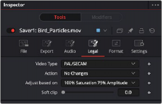
Saver Legal tab
Use this menu to select the standard to be used for broadcast legal color correction. NTSC, NHK, or PAL/SECAM can be chosen.
Use this menu to choose how Fusion treats illegal colors in the image.
— Adjust to Legal: This causes the images to be saved with legal colors relevant to the Video Type selected.
— Indicate as Black: This causes the illegal colors to be displayed as black in the views.
— Indicate as White: This causes the illegal colors to be displayed as white in the views.
— No Changes: This causes the images to be saved unaffected.
This menu is used to choose whether Fusion makes legal the image to 75% or 100% amplitude. Very few broadcast markets permit 100% amplitude, but for the most part this should be left to 75%.
The Soft Clip control is used to draw values that are out of range back into the image. This is done by smoothing the conversion curve at the top and bottom of the curve, allowing more values
to be represented.
![]()
Format Tab
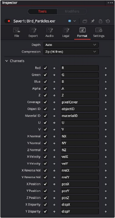
Saver Format tab
The Format tab contains information, options, and settings specific to the image format being saved. The controls for an EXR sequence is entirely different from the ones displayed when a MOV file is saved.
EXR is displayed above for reference.

When the Saver node is set to DPX, it’s important to understand the reason for the Bypass Conversion > Data is Linear option. When saving log data into a DPX, and not using the Saver’s node’s own lin-log conversion (that is, Bypass Conversion is checked), the Data
Is Linear option should be off. This indicates whether the reason for checking Bypass Conversion is because the data is linear, or whether it’s already log.
If Data Is Linear is enabled, then the DPX is marked in its header as containing linear data. In turn, that means that when the DPX is loaded back into Fusion, or into other apps that evaluate the header, those apps think the data is linear and do not perform any log-lin conversion.
Common Controls
The Settings tab controls are common to both Loader and Saver nodes, so their descriptions can be found in “The Common Controls” section at the end of this chapter.
This menu, sometimes considered source image clipping, defines how the edges of the image should be treated.
— Frame: The default Frame setting clips to the parts of the image visible within its visible dimensions. It breaks any infinite-workspace behavior. If the upstream DoD is smaller than the frame, the remaining areas in the frame are treated as black/transparent.
![]()
— None: This setting does not perform any source image clipping at all. This means that any data that would normally be needed outside the upstream DoD is treated as black/transparent. Be aware that this might create humongous images which can consume a considerable amount of disk space. So you should use this option only if really needed.
For more information about ROI, DoD, and Infinite Workspace, see Chapter 69, “Using Viewers.” in the DaVinci Resolve Reference Manual, or Chapter 7 in the Fusion Reference Manual.
When enabled, this control causes the Alpha channel to be saved into the color channels as a grayscale image. This completely overwrites any existing color information.
This menu is used to set the Color Space of the output file so you could, for example, color space convert images from linear to Rec709, etc., thereby delivering linear EXRs, 709 Quicktimes, etc. from a single source. The images are not being converted in the Comp, only in the images saved to disk are converted.
— Auto: Passes along any metadata that might be in the rendered image.
— Space: Allows the user to set the color space based on the output format.