< Previous | Contents | Next >
The Threshold range control can be used to clip the bitmap image. Increasing the low range control will clip pixels below the specified value to black (0.0). Decreasing the high range control will force pixels higher than the specified value to white (1.0).
This control has no effect unless the input image contains a Material or Object ID channel. When toggled on, the Object ID and Material ID are used to create a mask based on the selected object or material. When toggled off, the regular color channels will generate the mask.
Common Controls
The Image and Settings tabs in the Inspector are also duplicated in other Mask nodes. These common controls are described in detail at the end of this chapter in “The Common Controls” section.
B-Spline Mask [BSp]
The B-Spline node
![]()
A B-Spline mask is identical to a Polygon mask in all respects except one. Where Polygon masks use Bézier splines, this mask node uses B-Splines. Where Bézier splines employ a central point and two handles to manage the smoothing of the spline segment, a B-Spline requires only a single point. This means that a B-Spline shape requires far fewer control points to create a nicely smoothed shape.
When first added to a node, the B-Spline mask consists of only Center control, which is visible onscreen. Points are added to the B-Spline by clicking in the viewer. Each new point is connected to the last one created, but instead of the spline going directly through each control point, B-Spline control points only influence the spline shape. The control point pulls the spline in its direction to create a smooth curve.
Like the Polygon mask tool, the B-Spline mask auto-animates. Adding this node to the Node Editor adds a keyframe to the current frame. Moving to a new frame and changing the shape creates a new keyframe and interpolate between the two defined shapes.
Inputs
The B-Spline mask node includes a single effect mask input.
— Effect Mask: The optional blue input expects a mask shape created by polylines, basic primitive shapes, paint strokes, or bitmaps masks. Connecting a mask to this input combines the masks. How masks are combined is handled in the Paint mode menu in the Inspector.
Basic Node Setup
The B-Spline node can be used to generate a single smooth spline shape or combined with other masks for more complex shapes. In the node tree below, the B-Spline mask is used to generate a smooth, curved shape as a garbage matte on the Delta Keyer.
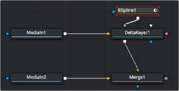
A B-Spline node generates a smooth, curved shape as a garbage matte
Inspector
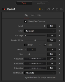
![]()
B-Spline Mask controls
Controls Tab
The Controls tab is used to refine how the B-Spline appears after drawing it in the viewer.
The Show View Controls checkbox is used to enable/disable the display of the mask’s onscreen controls in the viewer. Onscreen controls, including center position, polylines, angles, and others, do not appear when this checkbox is disabled, even when the node is selected.

NOTE: Lowering the level of a mask lowers the values of all pixels covered by the mask in the mask channel. For example, if a Circle mask is placed over a Rectangle mask, lowering the level of the Circle mask lowers the values of all of the pixels in the mask channel, even though the Rectangle mask beneath it is still opaque.
NOTE: Lowering the level of a mask lowers the values of all pixels covered by the mask in the mask channel. For example, if a Circle mask is placed over a Rectangle mask, lowering the level of the Circle mask lowers the values of all of the pixels in the mask channel, even though the Rectangle mask beneath it is still opaque.
NOTE: Lowering the level of a mask lowers the values of all pixels covered by the mask in the mask channel. For example, if a Circle mask is placed over a Rectangle mask, lowering the level of the Circle mask lowers the values of all of the pixels in the mask channel, even though the Rectangle mask beneath it is still opaque.
The Level control sets the transparency level of the pixels in the mask channel. When the value is 1.0, the mask is completely opaque (unless it has a soft edge). Lower values cause the mask to be partially transparent. The result is identical to lowering the blend control of an effect.
This control selects the filtering algorithm used when applying Soft Edge to the mask.
— Box: This is the fastest method but at reduced quality. Box is best suited for minimal amounts of blur.
— Bartlett: Otherwise known as a Pyramid filter, Bartlett makes a good compromise between speed and quality.
— Multi-box: When selecting this filter, the Num Passes slider appears and lets you control the quality. At 1 and 2 passes, results are identical to Box and Bartlett, respectively. At 4 passes and above, results are usually as good as Gaussian, in less time and with no edge “ringing.”
— Gaussian: The Gaussian filter uses a true Gaussian approximation and gives excellent results, but it is a little slower than the other filters. In some cases, it can produce an extremely slight edge “ringing” on floating-point pixels.
![]()
Use the Soft Edge slider to blur (feather) the mask, using the selected filter. Higher values cause the edge to fade off well beyond the boundaries of the mask. A value of 0.0 creates a crisp, well- defined edge.
The Border Width control adjusts the thickness of the mask’s edge. When the solid checkbox is toggled on, the border thickens or narrows the mask. When the mask is not solid, the mask shape draws as an outline, and the width uses the Border Width setting.
Connecting a mask to the effect mask input displays the Paint mode menu. The Paint mode is used to determine how the incoming mask for the effect mask input and the mask created in the node are combined.
— Merge: Merge is the default for all masks. The new mask is merged with the input mask.
— Add: The mask’s values add to the input mask’s values.
— Subtract: In the intersecting areas, the new mask values subtract from the input mask’s values.
— Minimum: Comparing the input mask’s values and the new mask, this displays the lowest (minimum) value.
— Maximum: Comparing the input mask’s values and the new mask, this displays the highest (maximum) value.
— Average: This calculates the average (half the sum) of the new mask and the input mask.
— Multiply: This multiplies the values of the input mask by the new mask’s values.
— Replace: The new mask completely replaces the input mask wherever they intersect. Areas that are zero (completely black) in the new mask do not affect the input mask.
— Invert: Areas of the input mask that are covered by the new mask are inverted; white becomes black and vice versa. Gray areas in the new mask are partially inverted.
— Copy: This mode completely discards the input mask and uses the new mask for all values.
— Ignore: This mode completely discards the new mask and uses the input mask for all values.
Selecting this checkbox inverts the entire mask. Unlike the Invert Paint mode, the checkbox affects all pixels, regardless of whether the new mask covers them or not.
When the Solid checkbox is enabled, the mask is filled to be transparent (white) unless inverted. When disabled, the spline is drawn as just an outline whose thickness is determined by the Border Width slider.
These controls adjust the position of the B-Spline mask.
Use the Size control to adjust the scale of the B-Spline effect mask, without affecting the relative behavior of the points that compose the mask or setting a keyframe in the mask animation.
Use these three controls to adjust the rotation angle of the mask along any axis.
![]()
The Fill Method menu offers two different techniques for dealing with overlapping regions of a polyline. If overlapping segments in a mask are causing undesirable holes to appear, try switching the setting of this control from Alternate to Non Zero Winding.
By default, all B-Spline masks are animated when they are created. The initial keyframe is set to the current time, and any changes to the shape at different times will create new keys.
Right-clicking on this label will display a contextual menu that offers options for removing or re-adding animation to the mask, or publishing and connecting the masks.
Adding Points
Adding Points to a B-Spline effect mask is relatively simple. Immediately after adding the node to the Node Editor, there are no points, but the tool will be in Click Append mode. Click once in the viewer wherever a point is required for the mask. Continue clicking to draw the shape of the mask.
When the shape is complete, click on the initial point again to close the mask.
When the shape is closed, the mode of the polyline changes to Insert and Modify. This allows you to add and adjust additional points on the mask by clicking the spline segments. To lock down the mask’s shape and prevent accidental changes, switch the Polyline mode to Done using the Polyline toolbar or contextual menu.
The tension of the control point determines the smoothness of a B-Spline. To adjust the tension of a B-Spline’s control points, select the point in the viewer, hold down the W key and drag the mouse pointer to the left and right to increase or decrease the tension of the curve through that point.
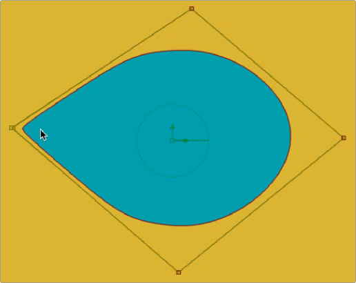
Adjusting Tension on a B-Spline
![]()
When a B-Spline mask is selected in the Node Editor, a toolbar appears above the viewer with buttons for easy access to the modes. Position the pointer over any button in the toolbar to display a tooltip that describes that button’s function.
![]()
B-Spline Mask Polygon toolbar
You can change the way the toolbar is displayed by right-clicking on the toolbar and selecting from the options displayed in the toolbar’s contextual menu.
The functions of the buttons in this toolbar are explained in depth in the Polylines section.
Common Controls
The Image and Settings tabs in the Inspector are also duplicated in other mask nodes. These common controls are described in detail at the end of this chapter in “The Common Controls” section.