< Previous | Contents | Next >
— Roto Assist: Enable the Roto Assist button when you begin painting with the Polyline Stroke tool. The polyline points snap to the closest edge as you click to add points to the shape. A cyan outline indicates the points that have snapped to an edge. There are three main Roto Assist options selectable through the drop down menu:
— Multiple Points: When enabled, a single click on a high contrast edge adds multiple points to define the entire edge, instead of having to add each point individually. This is a one time only click. The second click reverts to single point edge detection.
— Distance 8: Opens a dialog where you can set the pixel range within which searching for an edge takes place.
— Reset: Used for resetting the snap attribute of all snapped points. After resetting, the points become unavailable for tracking.
Change the way the toolbar is displayed by right-clicking on the toolbar and selecting from the options displayed in the toolbar’s contextual menu. The functions of the buttons in this toolbar are explained in depth in the Polylines chapter.
Ranges Mask [Rng]
The Ranges node
![]()
Ranges Mask Node Introduction
Similar to Bitmap mask, the Ranges mask allows images from the node tree to act as masks for nodes and effects. Instead of creating a simple luminance-based mask from a given channel, Ranges allows spline-based selection of low, mid and high ranges, akin to Color Corrector.
Inputs
The Ranges mask node includes two inputs in the Node Editor.
— Input: The orange input accepts a 2D image from which the mask will be created.
— Effect Mask: The optional blue input expects a mask shape created by polylines, basic primitive shapes, paint strokes, or bitmaps masks. Connecting a mask to this input combines the masks. How masks are combined is handled in the Paint mode menu in the Inspector.
Basic Node Setup
The Ranges node is not required for connecting an image into the effect mask input, but like the Bitmap node, it does provide options that are otherwise unavailable. It allows for selecting channels other than RGBA for the mask, as well as softness and clipping. In the node tree below, the Ranges node takes the composite out of the merge, creating a mask for the color correction.
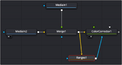
A Ranges node selects a specific range in the image to create a mask.
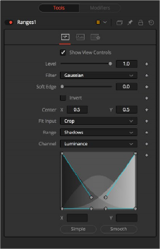
Inspector
![]()
Rangers Mask controls
Controls Tab
The Controls tab is used to refine how the image connected to the orange input converts into the ranges mask.
The Show View Controls checkbox is used to enable/disable the display of the mask’s onscreen controls in the viewer. Onscreen controls, including center position, polylines, angles, and others, do not appear when this checkbox is disabled, even when the node is selected.
NOTE: Lowering the level of a mask lowers the values of all pixels covered by the mask in the mask channel. For example, if a Circle mask is placed over a Rectangle mask, lowering the level of the Circle mask lowers the values of all of the pixels in the mask channel, even though the Rectangle mask beneath it is still opaque.
NOTE: Lowering the level of a mask lowers the values of all pixels covered by the mask in the mask channel. For example, if a Circle mask is placed over a Rectangle mask, lowering the level of the Circle mask lowers the values of all of the pixels in the mask channel, even though the Rectangle mask beneath it is still opaque.
NOTE: Lowering the level of a mask lowers the values of all pixels covered by the mask in the mask channel. For example, if a Circle mask is placed over a Rectangle mask, lowering the level of the Circle mask lowers the values of all of the pixels in the mask channel, even though the Rectangle mask beneath it is still opaque.
The Level control sets the transparency level of the pixels in the mask channel. When the value is 1.0, the mask is completely opaque (unless it has a soft edge). Lower values cause the mask to be partially transparent. The result is identical to lowering the blend control of an effect.
This control selects the filtering algorithm used when applying Soft Edge to the mask.
— Box: This is the fastest method but at reduced quality. Box is best suited for minimal amounts of blur.
— Bartlett: Otherwise known as a Pyramid filter, Bartlett makes a good compromise between speed and quality.
— Multi-box: When selecting this filter, the Num Passes slider appears and lets you control the quality. At 1 and 2 passes, results are identical to Box and Bartlett, respectively. At 4 passes and above, results are usually as good as Gaussian, in less time and with no edge “ringing.”
— Gaussian: The Gaussian filter uses a true Gaussian approximation and gives excellent results, but it is a little slower than the other filters. In some cases, it can produce an extremely slight edge “ringing” on floating-point pixels.
![]()
Use the Soft Edge slider to blur (feather) the mask, using the selected filter. Higher values cause the edge to fade off well beyond the boundaries of the mask. A value of 0.0 creates a crisp, well- defined edge.
Connecting a mask to the effect mask input displays the Paint mode menu. The Paint mode is used to determine how the incoming mask for the effect mask input and the mask created in the node are combined.
— Merge: Merge is the default for all masks. The new mask is merged with the input mask.
— Add: The mask’s values add to the input mask’s values.
— Subtract: In the intersecting areas, the new mask values subtract from the input mask’s values.
— Minimum: Comparing the input mask’s values and the new mask, this displays the lowest (minimum) value.
— Maximum: Comparing the input mask’s values and the new mask, this displays the highest (maximum) value.
— Average: This calculates the average (half the sum) of the new mask and the input mask.
— Multiply: This multiplies the values of the input mask by the new mask’s values.
— Replace: The new mask completely replaces the input mask wherever they intersect. Areas that are zero (completely black) in the new mask do not affect the input mask.
— Invert: Areas of the input mask that are covered by the new mask are inverted; white becomes black and vice versa. Gray areas in the new mask are partially inverted.
— Copy: This mode completely discards the input mask and uses the new mask for all values.
— Ignore: This mode completely discards the new mask and uses the input mask for all values.
Selecting this checkbox inverts the entire mask. Unlike the Invert Paint mode, the checkbox affects all pixels, regardless of whether the new mask covers them or not.
These controls adjust the position of the ranges mask.
This menu is used to select how the image source is treated if it does not fit the dimensions of the generated mask.
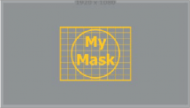
For example, below, a 720 x 576 image source (yellow) is used to generate a 1920 x 1080 mask (gray).
— Crop: If the image source is smaller than the generated mask, it is placed according to the X/Y controls, masking off only a portion of the mask. If the image source is larger than the generated mask it is placed according to the X/Y controls and cropped off at the borders of the mask.
![]()
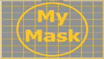
— Stretch: The image source is stretched in X and Y to accommodate the full dimensions of the generated mask. This might lead to visible distortions of the image source.
— Inside: The image source is scaled uniformly until one of its dimensions (X or Y) fits the inside dimensions of the mask. Depending on the relative dimensions of the image source and mask background, either the image source’s width or height may be cropped to fit the respective dimension of the mask.
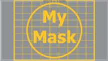
— Width: The image source is scaled uniformly until its width (X) fits the width of the mask. Depending on the relative dimensions of the image source and mask, the image source’s Y dimension might not fit the mask’s Y dimension, resulting in either cropping of the image source in Y or the image source not covering the mask’s height entirely.
— Height: The image source is scaled uniformly until its height (Y) fits the height of the mask. Depending on the relative dimensions of the image source and mask, the image source’s X dimension might not fit the mask’s X dimension, resulting in either cropping of the image source in X or the image source not covering the mask’s width entirely.
![]()
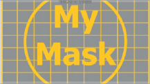
— Outside: The image source is scaled uniformly until one of its dimensions (X or Y) fits the outside dimensions of the mask. Depending on the relative dimensions of the image source and mask, either the image source’s width or height may be cropped or not fit the respective dimension of the mask.
The Channel menu determines the Channel of the input image used to create the mask. Choices include the red, green, blue, and alpha channels; the hue, luminance, or saturation values; or the auxiliary coverage channel of the input image (if one is provided).
These buttons are used to select which range is output by the node as a mask. White pixels represent pixels that are considered to be part of the range, and black pixels are not included in the range. For example, choosing Shadows would show pixels considered to be shadows as white, and pixels that are not shadows as black. Mid gray pixels are only partly in the range and do not receive the full effect of any color adjustments to that range.