< Previous | Contents | Next >
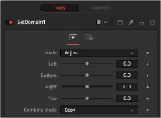
Defines the right border of the DoD. Higher values on this slider move the right border toward the left, excluding more data from the right margin.
1 represents the right border of the image; 0 represents the left border. In Set mode, the slider defaults to 1 (right border).
Defines the top border of the DoD. Higher values on this slider move the top border toward the bottom, excluding more data from the top margin.
1 represents the top border of the image; 0 represents the bottom border. In Set mode, the slider defaults to 1 (top border).
The Set Domain Controls tab in Adjust mode
Common Controls
![]()
The Settings tab in the Inspector is also duplicated in other miscellaneous nodes. These common controls are described in detail at the end of this chapter in “The Common Controls” section.
Time Speed [TSpd]
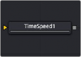
The Time Speed node
Time Speed Node Introduction
The Time Speed node allows image sequences to be sped up, slowed down, reversed, or delayed. Image Interpolation offers smooth, high-quality results. Time Speed should be used for static speed changes or to introduce delays in the footage. To apply animated changes in time, such as accelerating or decelerating time, use a Time Stretcher instead.
When operating in Flow mode, Optical Flow data is required. This node does not generate optical flow directly. You have to create it upstream using an Optical Flow node or by loading the forward/reverse vector channels from the image.
TimeSpeed does not interpolate the aux channels but instead destroys them. In particular, the Vector/ BackVector channels are consumed and destroyed after computation.
Add an Optical Flow after the Time Speed node if you want to generate flow vectors for the retimed footage.
Inputs
The single input on the Time Speed node is used to connect a 2D image that will be retimed.
— Input: The orange input is used for the primary 2D image that will be retimed.
Basic Node Setup
The Time Speed node setup is as simple as connecting a 2D image into the orange background input of the node.
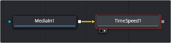
A MediaIn node having its speed changed in the Time Speed node.
![]()
Inspector
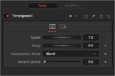
The Time Speed Controls tab
This control is used to adjust the Speed, in percentage values, of the outgoing image sequence. Negative values reverse the image sequence. 200% Speed is represented by a value of 2.0, 100% by 1.0, 50% by 0.5, and 10% by 0.1.
The Speed control cannot be animated.
Use this control to Delay the outgoing image sequence by the specified number of frames. Negative numbers offset time back, and positive numbers advance time.
This menu determines the how the time speed is processed in order to improve its visual playback quality, especially in the case of clips that are slowed down. There are three choices in the menu.
— Nearest: The most processor efficient and least sophisticated method of processing; frames are either dropped for fast motion or duplicated for slow motion.
— Blend: Also processor efficient, but can produce smoother results; adjacent duplicated frames are dissolved together to smooth out slow or fast motion effects.
— Flow: The most processor intensive but highest quality method of speed effect processing. Using vector channels pre-generated from an Optical Flow node, new frames are generated to create slow or fast motion effects. The result can be exceptionally smooth when motion in a clip is linear. However, two moving elements crossing in different directions or unpredictable camera movement can cause unwanted artifacts.
This slider is displayed only when Interpolation is set to Blend. The slider controls the strength of the interpolated frames on the current frame. A value of 0.5 blends 50% of the frame before and 50% of the frame ahead and 0% of the current frame.
This menu is displayed only when Interpolation is set to Flow. The Depth Ordering is used to determine which parts of the image should be rendered on top. This is best explained by example.
![]()
In a locked-off camera shot where a car is moving through the frame, the background does not move, so it produces small, or slow, vectors. The car produces larger, or faster, vectors.
The Depth Ordering, in this case, is Fastest on Top, since the car draws over the background.
In a shot where the camera pans to follow the car, the background has faster vectors, and the car has slower vectors, so the Depth ordering method would be Slowest on Top.
This checkbox is displayed only when Interpolation is set to Flow. Under certain circumstances, this option can remove the transparent gaps that may appear on the edges of interpolated frames. Clamp Edges can cause a stretching artifact near the edges of the frame that is especially visible with objects moving through it or when the camera is moving.
Because of these artifacts, it is a good idea to use clamp edges only to correct small gaps around the edges of an interpolated frame.
This slider is only displayed when Interpolation is set to Flow and Clamp Edges is enabled. It helps to reduce the stretchy artifacts that might be introduced by Clamp Edges.
If you have more than one of the Source Frame and Warp Direction checkboxes turned on, this can lead to doubling up of the stretching effect near the edges. In this case, you’ll want to keep the softness rather small at around 0.01. If you have only one checkbox enabled, you can use a larger softness at around 0.03.