< Previous | Contents | Next >
An External Matte Saver node added as a separate branch in a node tree to render the mattes
Inspector
The External Matte Saver Controls tab
![]()
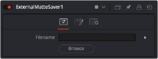
Controls Tab
The Controls tab is used to name the saved file and determine where on your hard drive the file is stored.
Enter the name you want to use for the EXR file in the Filename field. At the end of the name, append the .exr extension to ensure that the file is saved as an EXR file.
Clicking the Browse button opens a standard file browser window where you can select the location to save the file.
The External Matte Saver Mattes tab
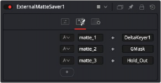
Mattes Tab
The Mattes tab is where you set up the number of mattes saved in the file, the name for each channel, and the RGBA channels saved from each input.
The Channels menu allows you to select which channels are saved in the matte. You can choose the alpha channel, the RGB channels, or the RGBA channels.
The Channels Name field allows you to customize the name of the matte channel you are saving. This name is displayed in DaVinci Resolve’s Color page.
The Node Name field displays the source of the matte. This is automatically populated when you connect a node to the input.
![]()
Clicking the Add button adds an input on the node and another set of fields for you to configure and name the new matte channel.
The External Matte Saver Settings tab
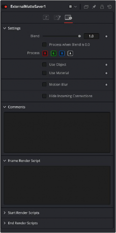
Settings Tab
The Settings Tab in the Inspector is similar to settings found in the Saver tool. The controls are consistent and work the same way as the Settings in other tools.
The Blend control is used to blend between the tool’s original image input and the tool’s final modified output image. When the blend value is 0.0, the outgoing image is identical to the incoming image.
Normally, this causes the tool to skip processing entirely, copying the input straight to the output.
The tool is processed even when the input value is zero. This can be useful if processing of this node is scripted to trigger another task, but the value of the node is set to 0.0.
These four buttons are used to limit the effect of the tool to specified color channels. This filter is often applied after the tool has been processed.
For example, if the Red button on a Blur tool is deselected, the blur is first applied to the image, and then the red channel from the original input is copied back over the red channel of the result.
There are some exceptions, such as tools for which deselecting these channels causes the tool to skip processing that channel entirely. Tools that do this generally possess a set of identical RGBA buttons on the Controls tab in the tool. In this case, the buttons in the Settings and the Controls tabs are identical.
Enabling the Apply Mask Inverted option inverts the complete mask channel for the tool. The mask channel is the combined result of all masks connected to or generated in a node.
Selecting this option causes the RGB values of the masked image to be multiplied by the mask channel’s values. This causes all pixels of the image not included in the mask (i.e., set to 0) to become black/transparent.
![]()
Some 3D software can render to file formats that support additional channels. Notably, the EXR file format supports Object ID and Material ID channels, which can be used as a mask for the effect. These checkboxes determine whether the channels are used, if present. The specific Material ID or Object ID affected is chosen using the next set of controls.
This checkbox appears only when the Use Object or Use Material checkboxes are selected. It toggles the method used to deal with overlapping edges of objects in a multi-object image. When enabled, the Coverage and Background Color channels are used to separate and improve the effect around the edge of the object. If this option is disabled (or no Coverage or Background Color channels are available), aliasing may occur on the edge of the mask.
For more information on the Coverage and Background Color channels, see Chapter 78, "Understanding Image Channels," in the DaVinci Resolve Reference Manual, or Chapter 16 in the Fusion Reference Manual.
Use these sliders to select which ID is used to create a mask from the object or material channels of an image. Use the Sample button in the same way as the Color Picker: to grab IDs from the image
displayed in the viewer. The image or sequence must have been rendered from a 3D software package with those channels included.
— Motion Blur: This toggles the rendering of Motion Blur on the tool. When this control is toggled on, the tool’s predicted motion is used to produce the motion blur caused by the virtual camera’s shutter. When the control is toggled off, no motion blur is created.
— Quality: Quality determines the number of samples used to create the blur. A quality setting of 2 causes Fusion to create two samples to either side of an object’s actual motion. Larger values produce smoother results but increase the render time.
— Shutter Angle: Shutter Angle controls the angle of the virtual shutter used to produce the motion blur effect. Larger angles create more blur but increase the render times. A value of 360 is the equivalent of having the shutter open for one full frame exposure. Higher values are possible and can be used to create interesting effects.
— Center Bias: Center Bias modifies the position of the center of the motion blur. This allows for the creation of motion trail effects.
— Sample Spread: Adjusting this control modifies the weighting given to each sample. This affects the brightness of the samples.
![]()
Enabling this checkbox can hide connection lines from incoming nodes, making a node tree appear cleaner and easier to read. When enabled, empty fields for each input on a node will be displayed in the Inspector. Dragging a connected node from the node tree into the field will hide that incoming connection line as long as the node is not selected in the node tree. When the node is selected in the node tree, the line will reappear.
The Comments field is used to add notes to a tool. Click in the empty field and type the text. When a note is added to a tool, a small red square appears in the lower-left corner of the node when the full tile is displayed, or a small text bubble icon appears on the right when nodes are collapsed. To see the note in the Node Editor, hold the mouse pointer over the node to display the tooltip.
Three Scripting fields are available on every tool in Fusion from the Settings tab. They each contain edit boxes used to add scripts that process when the tool is rendering. For more details on scripting nodes, please consult the Fusion scripting documentation.