< Previous | Contents | Next >
The Position parameter allows you to position the starting point of the shape. When used in conjunction with the Length parameter, it positions the gap in the outline.
The Length parameter controls the end position of the outline. A length of 1.0 is a closed shape. Setting the length below 1.0 creates an opening or gap in the outline. Keyframing the Length parameters allows you to create write-on style animations.
Common Controls
The Settings tab in the Inspector is common to all Shape nodes. These common controls are described in detail at the end of this chapter in “The Common Controls” section.
sPolygon [sPly]
The sPolygon node
![]()
The sPolygon tool allows users to draw custom shapes. Through intuitive point manipulation, this tool allows users to effortlessly generate intricate forms, curves, and lines, which tie in with the existing shape tools in Fusion. It provides the freedom to design custom elements, making it a valuable tool in motion graphics design.
Inputs
This node generates shapes and does not have any inputs.
Basic Node Setup
The sPolygon node is a shape generator, meaning it generates a shape and therefore has no inputs. The output of the sPolygon can go into a sRender for viewing and further compositing or, more likely, connect to another Shape node like sGrid or sDuplicate.
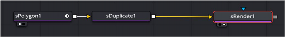
An sPolygon node connecting to an sDuplicate node, and then viewed using an sRender node
Inspector
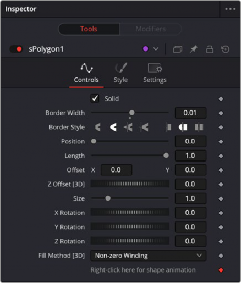
The sPolygon Controls tab
Controls
The Controls tab is used to define the polygon characteristics, including fill, border, size, and position.
When enabled, the Solid checkbox fills the rectangle shape with the color defined in the Style tab. When disabled, an outline created by the Border Width control is displayed, and the center is made transparent.
![]()
This parameter expands or contracts the border around the shape. Although it can be used when the Solid checkbox is enabled, it is primarily used to determine the outline thickness when the checkbox is disabled.
The Border Style parameter controls how the sides of the rectangle join at the corners. There are three styles provided as options. Bevel squares off the corners. Round creates rounded corners. Miter maintains pointed corners.
The cap styles can create lines with flat, rounded, or squared ends. Flat caps have flat, squared ends, while rounded caps have semi-circular ends. Squared caps have projecting ends that extend half the line width beyond the end of the line.
The caps are not visible unless the length is below 1.0.
The Position parameter is only displayed when the Solid checkbox is disabled. It allows you to position the starting point of the shape. When used in conjunction with the Length parameter, it positions the gap in the outline.
The Length parameter is only displayed when the Solid checkbox is disabled. A length of 1.0 is a closed shape. Setting the length below 1.0 creates an opening or gap in the outline. Keyframing the Length parameters allows you to create write-on style animations.
These parameters are used to position the shape left, right, up, and down in the frame. The shape starts in the center of the frame, and the parameters are used to offset the position. The offset coordinates are normalized based on the width of the frame. So an X offset of 0.0 is centered and a value of 0.5 places the center of the shape directly on the right edge of the frame.
If used with the 3D toolset, you can offset the polygon in back and forth along the Z-axis by adjusting these controls.
Use the Size control to adjust the scale of the polygon shape, without affecting the relative behavior of the points that compose the shape or setting a keyframe in the shape animation.
Use these three controls to adjust the rotation angle of the shape along any axis. Fill Method [3D]
The Fill Method menu offers two different techniques for dealing with overlapping regions of a polyline. If overlapping segments in a shape are causing undesirable holes to appear, try switching the setting of this control from Alternate to Non Zero Winding.
![]()
Style Tab
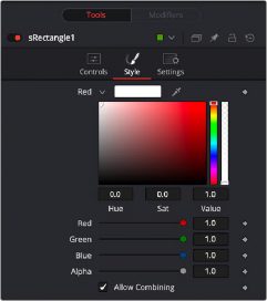
The sPolygon Style tab
Style
The Style tab is used to assign color to the shape and control its transparency.