< Previous | Contents | Next >
The Export button will create a basic setup that can be used for 3D match moving:
— A Camera 3D with animated translation and rotation that matches the motion of the live-action camera and an attached image plane.
— A Point Cloud 3D containing the reconstructed 3D positions of the tracks.
— A Shape 3D set to generate a ground plane.
— A Merge 3D merging together the camera, point cloud, and ground plane. When the Merge 3D is viewed through the camera in a 3D viewer, the 3D locators should follow the tracked footage.
— A Renderer 3D set to match the input footage.
The export of individual nodes can be enabled/disabled in the Export Options tab.
When this button is clicked, the previously exported nodes are updated with any new data generated. These previously exported nodes are remembered in the Previous Export section at the bottom of this section. Here’s an example of how this is handy:
1 Solve the camera and export.
2 Construct a complex Node Editor based around the exported nodes for use in set extension.
3 The camera is not as accurate as preferred or perhaps the solver is rerun to add additional tracks to generate a denser point cloud. Rather than re-exporting the Camera 3D and Point Cloud 3D nodes and connecting them back in, just press the Update Previous Export button to “overwrite” the existing nodes in place.
![]()
This will cause the already exported nodes (Camera 3D, Point Cloud 3D, Lens Distort, Renderer 3D, and the ground plane) to auto update on each solve.
3D Scene Transform
Although the camera is solved, it has no idea where the ground plane or center of the scene is located. By default, the solver will always place the camera in Fusion’s 3D virtual environment so that on the first frame it is located at the origin (0, 0, 0) and is looking down the -Z axis. You have the choice to export this raw scene without giving the Camera Tracker any more information, or you can set the ground plane and origin to simplify your job when you begin working in the 3D scene. The 3D Scene Transform controls provide a mechanism to correctly orient the physical ground plane in the footage with the virtual ground plane in the 3D viewer. Adjusting the 3D Scene Transform does not modify

NOTE: If you export the scene and then make changes in the 3D Scene Transform, it is important to manually click Update Previous Export to see the results in the exported nodes.
NOTE: If you export the scene and then make changes in the 3D Scene Transform, it is important to manually click Update Previous Export to see the results in the exported nodes.
NOTE: If you export the scene and then make changes in the 3D Scene Transform, it is important to manually click Update Previous Export to see the results in the exported nodes.
the camera solve but simply repositions the 3D scene to best represent the position of the live- action camera.
The Aligned/Unaligned menu locks or unlocks the origin and ground plane settings. When set to Unaligned, you can select the ground plane and origin either manually or by selecting locators in the viewer. When in unaligned mode, a 3D Transform control in the 3D viewer can be manually manipulated to adjust the origin.
Once alignment of the ground plane and origin has been completed, the section is locked by switching the menu to Aligned.
When set to unaligned, buttons labeled Set from Selection are displayed under the Origin, Orientation, and Scale sections. Clicking these buttons takes the selecting locators in the viewer and aligns the ground plane or origin based on the selection.
For instance, to set the ground plane, do the following:
1 After solving, set the 3D Scene Transform menu to Unaligned.
2 Find a frame where the ground plane is at its largest and clearest point.
3 In the viewer, drag a selection rectangle around all the ground plane locators.
4 Hold Shift and drag again to add to the selection.
5 In the Orientation section, make sure the Selection Is menu correctly matches the orientation of the selected locators.
6 Click the Set from Selection button located under the Orientation parameters.
7 Set the 3D Scene Transform menu back to Aligned.

TIP: When selecting points for the ground plane, it is helpful to have the Camera Tracker node viewed in side-by-side 2D and 3D views. It may be easier to select tracks belonging to the ground by selecting tracks from multiple frames in the 2D viewer rather than trying to box select locators in the 3D viewer.
TIP: When selecting points for the ground plane, it is helpful to have the Camera Tracker node viewed in side-by-side 2D and 3D views. It may be easier to select tracks belonging to the ground by selecting tracks from multiple frames in the 2D viewer rather than trying to box select locators in the 3D viewer.
TIP: When selecting points for the ground plane, it is helpful to have the Camera Tracker node viewed in side-by-side 2D and 3D views. It may be easier to select tracks belonging to the ground by selecting tracks from multiple frames in the 2D viewer rather than trying to box select locators in the 3D viewer.
To get the best result when setting the ground plane, try to select as many points as possible belonging to the ground and having a wide separation.
![]()
Setting the origin can help you place 3D objects in the scene with more precision. To set the origin, you can follow similar steps, but only one locator is required for the origin to be set. When selecting a locator for the origin, select one that has a very low solve error.
These controls let you adjust the ground plane for the scene, which is a crucial step in making sure the composite looks correct.
Color | Will set the color of the ground plane. |
Size | Controls how big the ground plane can be set. |
Subdivision Level | Shows how many polygons are in the ground plane. |
Wireframe | Sets whether the ground plane is set as wireframe or solid surface when displayed in 3D. |
Adjusts how wide the lines will draw in the view. | |
Offset | By default, the center of the ground plane is placed at the origin (0, 0, 0). This can be used to shift the ground plane up and down along the y-axis. |
Provides a checkbox list of what will be exported as nodes when the Export button is pressed. These options are Camera, Point Cloud, Ground Plane, Renderer, Lens Distortion, and Enable Image Plane in the camera.
The Animation menu allows you to choose between animating the camera and animating the point cloud. Animating the camera leaves the point cloud in a locked position while the camera is keyframed to match the live-action shot. Animating the point cloud does the opposite. The camera is locked in position while the entire point cloud is keyframed to match the live-action shot.
When the Update Previous Export button is clicked, the previously exported nodes listed here are updated with any new data generated (this includes the camera path and attributes, the point cloud, and the renderer).
Options Tab
![]()
The Options tab lets you customize the Camera Tracker’s onscreen controls so you can work most effectively with the scene material you have.
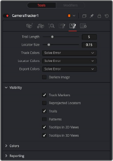
The Camera Tracker Options tab
Displays trail lines of the tracks overlaid on the viewer. The amount of frames forward and back from the current frame is set by length.