< Previous | Contents | Next >
The USD Shape node
uShape Node Introduction
The uShape node is used to produce several basic primitive 3D shapes, including capsule, torus, planes, cubes, spheres, and cylinders.
Inputs
— None.
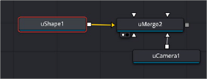
Basic Node Setup
![]()
The uShape node generates a 3D shape that is merged with a uCamera node to adjust the view.
Inspector
The USD Shape Controls
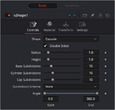
Controls Tab
This menu allows you to select the primitive geometry produced by the Shape 3D node. The remaining controls in the Inspector change to match the selected shape.
The Shape primitives are Capsule, Cone, Cube, Cylinder, Ico sphere, Plane, Sphere and Torus.
This will make the polygons have two faces and receive lighting on both sides.
Only for Plane and Cube shapes. If this checkbox is selected, the width, height, and depth controls are locked together as a single size slider. Otherwise, individual controls over the size of the shape along each axis are provided.
Only for Plane and Cube shapes. Used to control the size of the shape.
When a Capsule, Sphere, Cylinder, Cone, or Torus is selected in the shape menu, this control sets the radius of the selected shape.
When a Capsule, Cone, or Cylinder is selected in the shape menu, this control sets the height of the selected shape.
![]()
When a cone is selected in the Shape menu, this control is used to define a radius for the top of a cone, making it possible to create truncated cones.
The Subdivision controls are used to determine the tessellation of the mesh on all shapes. The higher the subdivision, the more vertices and polygons in each shape.
The Subdivision Scheme defines which algorithm is used to tessellate the polygons in the shapes. The methods are None, Bilinear, Loop and Catmull-Clark.
When the Capsule, Cone, Cylinder, Sphere, or Torus shape is selected in the Shape menu, this range control determines how much of the shape is drawn. A start angle of 180° and end angle of 360° would only draw half of the shape.
When a Sphere or Torus is selected in the Shape menu, this range control is used to crop or slice the object by defining a latitudinal subsection of the object.
When Cylinder or Cone is selected in the Shape menu, the Bottom Cap and Top Cap checkboxes are used to determine if the end caps of these shapes are created or if the shape is left open
When the Torus is selected in the Shape menu, Section controls the thickness of the tube making up the torus.
Material Tab
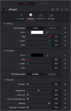
The USD Shape Material controls
![]()
Diffuse describes the base surface characteristics without any additional effects like reflections or specular highlights.
— Color: Provides controls to modify the shape’s diffuse color.
— Texture: This control allows you to use a source image as the diffuse surface color. Use the Browse button to open the file browser and select an image file.
Emissive adds a global lighting effect to a shape, creating a layer of color over the existing texture. It can be adjusted to different levels of intensity and can be used to simulate the emission of light.
Lets you set the mode between Metallic and Specular.
— Metallic: When enabled, this control shows the Metallic slider. The Metallic slider adds a reflective quality to objects, creating the appearance of metal. It enhances the reflective properties of a shape.
— Specular: When enabled, this shows the Specular Color controls. Specular Color determines the color of light that reflects from a shiny surface. The more specular a material is, the glossier it appears.