
< Previous | Contents | Next >
This controls the intensity, or strength, of the simulated light, causing bright and dim areas to form according to the contour of the refraction image. Higher values cause the bright and dim areas to be more pronounced.
This sets the angle of the simulated light source.
This widens the Displacement effect and takes the edge off the Refraction map. Higher values cause the ridges or edges to spread out.
NOTE: The Radial mode pushes pixels inward or outward from a center point, based on pixel values from the Displacement map. The XY mode uses two different channels from the map to displace pixels horizontally and vertically, allowing more precise results. Using the XY mode, the Displace node can even accomplish simple morphing effects. The Light controls allow directional highlighting of refracted pixels for simulating a beveled look.
NOTE: The Radial mode pushes pixels inward or outward from a center point, based on pixel values from the Displacement map. The XY mode uses two different channels from the map to displace pixels horizontally and vertically, allowing more precise results. Using the XY mode, the Displace node can even accomplish simple morphing effects. The Light controls allow directional highlighting of refracted pixels for simulating a beveled look.
NOTE: The Radial mode pushes pixels inward or outward from a center point, based on pixel values from the Displacement map. The XY mode uses two different channels from the map to displace pixels horizontally and vertically, allowing more precise results. Using the XY mode, the Displace node can even accomplish simple morphing effects. The Light controls allow directional highlighting of refracted pixels for simulating a beveled look.
Select the channel from the refraction image to use as the simulated light source. Select from Color, Red, Green, Blue, Alpha, or Luminance channels.
Common Controls
![]()
The Settings tab in the Inspector is also duplicated in other Warp nodes. These common controls are described in detail at the end of this chapter in “The Common Controls” section.
Drip [DRP]
The Drip node
Drip Node Introduction
The Drip node creates a ripple effect over the entire image, which has the potential to animate outward from a central source. There are a variety of different Drip effects from which to choose.
Inputs
The two inputs on the Drip node are used to connect a 2D image and an effect mask, which can be used to limit the warped area.
— Input: The orange input is used for the primary 2D image that is warped.
— Effect Mask: The blue input is for a mask shape created by polylines, basic primitive shapes, paint strokes, or bitmaps from other tools. Connecting a mask to this input limits the warping to only those pixels within the mask. An effects mask is applied to the tool after the tool is processed.
Basic Node Setup
Below, the Drip node is used to make rippling water-style effects using a MediaIn node.
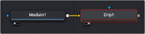
The Drip node can be connected directly after a MediaIn node or any node providing a 2D output.
Inspector
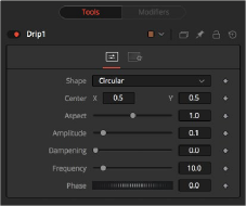
![]()
The Drip Controls tab
Controls Tab
The Controls tab is used to change the style, position, size , strength, and phase for animating the “ripples” of the Drip.
Use this control to select the shape of the Drip.
This creates circular ripples. This is the default Drip mode.
This creates even-sided quadrilateral drips.
This creates a randomly dispersed noise that distorts your image and is similar to a particle effect.
This creates horizontal waves that move in one direction.
This creates vertical waves that move in one direction.
This creates a Drip effect that looks like a diamond shape with inverted, curved sides (an exponential curve flipped and mirrored).
This creates an eight-way symmetrical star-shaped ripple that acts as a kaleidoscope when the phase is animated.
This creates a star-shaped ripple that emits from a fixed pattern.
Use this control to position the center of the Drip effect in the image. The default is 0.5, 0.5, which centers the effect in the image.
Control the aspect ratio of the various Drip shapes. A value of 1.0 causes the shapes to be symmetrical. Smaller values cause the shape to be taller and narrower, while larger values cause shorter and wider shapes.
![]()
The Amplitude of the Drip effect refers to the peak height of each ripple. Use the slider to change the amount of distortion the Drip applies to the image. A value of 0.0 gives all ripples no height and therefore makes the effect transparent. A maximum Amplitude of 10 makes each ripple extremely visible and completely distorts the image. Higher numbers can be entered via the text entry boxes.
Controls the Dampening, or falloff, of the amplitude as it moves away from the center of the effect. It can be used to limit the size or area affected by the Drip.
This changes the number of ripples emanating from the center of the Drip effect. A value of
0.0 indicates no ripples. Move the slider up to a value of 100 to correspond with the density of desired ripples.
This controls the offset of the frequencies from the center. Animate the Phase value to make the ripple emanate from the center of the effect.