< Previous | Contents | Next >
— Overlay Placement: These controls let you set the initial transform options for the image you want to overlay on the mesh.
— Go To Reference: Moves the playhead to the selected reference frame.
— Set to Current: Sets the current frame under the playhead as the reference frame.
— Reference Frame: Shows the frame number at which the overlay is originally positioned and un-warped (the point from which the warp to every other frame is calculated). The positioning controls appear on screen when the clip is at the reference frame. A frame where the surface’s view is largest and least warped is the best starting point for rendering onto other frames.
— Positioning: Lets you choose how to adjust the overlay position.
— Sliders: Choosing this option exposes a set of transform sliders (X/Y position, zoom, rotate, etc.) that let you manipulate the overlay’s initial position.
— Interactive Canvas: Choosing this option exposes draggable frame controls in the Viewer, allowing you to transform the overlay using mouse controls. The Viewers shows a large grid with 9 regions; you can drag in any of them to move, skew, or warp the overlay.
— Interactive Pins: Adjusting the image in this mode is done by manually placing control points, called pins, in the Timeline Viewer. Adding one pin only gives you position control. At least two points are required for scaling and rotation. Dragging on one of the pins scales or rotates the image around the other pin. Using three pins, you can create perspective distortions by dragging any one of the pins. You can add up to four pins for unique corner pinning distortions.
— Reset Position: Resets the on-screen overlay back to its default state.
— Interaction Overlays: These buttons control the visibility of the mesh overlays on the Viewer.
— Show: Shows the mesh at all times.
— Hide on Drag: Shows the mesh until a point is dragged, then it is hidden, allowing you to see the surface underneath for fine adjustments.
— Hide: Hides the mesh at all times.
— Compositing: Lets you set the composite blend mode for the overlay operation. For more detailed information on each blend mode, see Chapter 50, “Compositing and Transforms in the Timeline.”
— Composite Type: A drop-down menu of all the possible composite operations.
— Opacity: This slider controls the transparency of the overlay.
![]()
Using the Surface Tracker
The Surface Tracker is a deep and versatile tool that can be used to realistically isolate a moving surface for a variety of effects. The examples below can get you started on discovering its uses.
Using the Surface Tracker to Composite a Logo onto a Fabric Surface
One of the more common use cases of the Surface Tracker is to overlay a still graphic on top of a moving surface and have the graphic behave realistically as the surface deforms and warps. In this example, we will add a simple logo to the back of a jacket.
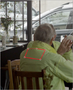
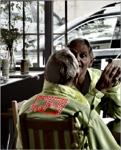
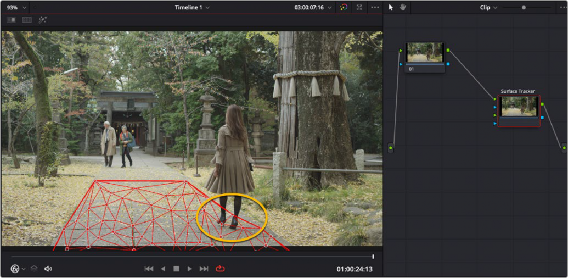
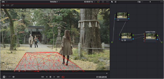
The first step is to define the boundary of where we want the surface analyzed. For best results, you need to place the boundary on the surface to be tracked, not around it, and try to find a frame where the surface is flat on to the camera and as large in the frame as possible.
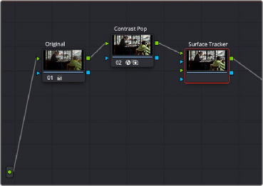
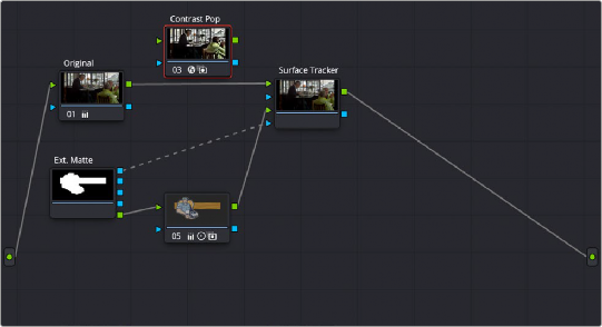
The next step is to define the Mesh within the surface to be warped. In this case, we will leave the Point Locations setting at Automatic to have the effect apply the mesh points. Ideally, there will be more than five mesh points for a good track. Unfortunately, this surface doesn’t have enough detail to make a good mesh, so we will temporarily add a Contrast Pop node before the Surface Tracker in order to artificially enhance its details.
Creating the initial boundary to isolate the surface of the jacket where the logo will be applied
![]()
By adding the Contrast Pop FX before the Surface Tracker input, we can artificially increase the detail inside the boundary, giving it a better surface to form the mesh.
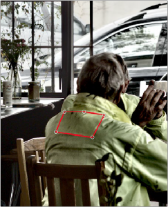
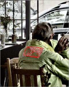
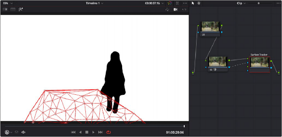
The Tracker analyzes the Mesh movement throughout the rest of the video clip.
Next, we will track the Mesh’s motion using the Track Forward button and leave the rest of the controls at their defaults. Note that the track continues to warp and fold correctly, even when the subject leans back in his chair.
With the surface now correctly analyzed, we no longer need the Contrast Pop node, so we can disconnect it at this point. Next, we will drag the logo (a .png file with transparency) from the Media Pool, over into the node tree, where it comes in as a matte. We then add a corrector node after the matte, so we can adjust the color/saturation/brightness, etc. of the logo.
Next, we set the RGB and Key connections of the nodes through the matte and corrector nodes, and into the second RGB and Key inputs of the Surface Tracker. This is shown on the node tree below:
![]()
The node tree, showing the layout of the RGB and Key inputs to composite the logo over the jacket
Now, moving to the Result section, we set the following parameter:
— Output: Warp Input 2 onto 1 - This will take the second RGB and Key input (logo) and deform it over the original image coming in to RGB input 1.
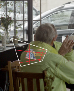
Then we will click on the Go To Reference button to take the clip to its reference frame, and in Positioning, use the Interactive - Canvas tool to reframe the logo to look like it’s on the same plane as the jacket.
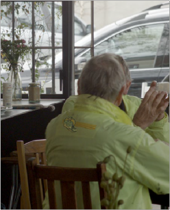
For the last step, we change the Composite Type from Normal to Overlay to make the logo blend in better to the surface of the jacket.
Notice how the logo is deformed by the mesh to wrap around the curves and folds of the jacket, and it tracks along with the man as he leans back in his chair.
Adjusting the logo in the Interactive Canvas mode to transform it to make it
appear it’s in the same plane as the jacket
![]()
The finished Surface Tracker composite; the logo now adheres to the curves and folds of the jacket and tracks along with the man as he shifts positions in his chair.
Tracking Using a Mask in the Surface Tracker
If there is an object occluding the surface to be tracked, then an input key can be used as a tracking mask to exclude the blocking object from the track. Areas of full alpha (completely white) in the Alpha channel are analyzed for tracking, while other areas are excluded. Any appropriate effect, window, or qualifier can be used as the Alpha channel generator. For example, in the shot below, the path has the surface mesh applied to it, however the woman walking over the path breaks the mesh tracking. By connecting a node’s key output with a Magic Mask applied to it that picks out the shape of the walking woman, then inverting that mask (so the woman is black, while her surroundings are white), the mesh ignores her legs and feet as they pass through it and only tracks points in the white areas (everything other than the woman).
A problem trying to track the path’s surface; as the woman walks through the mesh, the points attach themselves to her feet instead of the path, breaking the tracking on the right side of the path.
![]()
By connecting an inverted key from a Magic Mask node of just the woman, the tracking ignores the woman walking through the mesh (anything black), and only tracks points in the white part of the Alpha channel.
The resulting mesh is now properly attached to the path’s right side and tracks correctly as she walks through it.
In the final step of the Surface Tracker, the overlay with alpha is composited over the original clip with alpha, so if using a tracking mask, it is recommended to disconnect it from the Surface Tracker’s key input after the tracking is complete.
Using the Surface Tracker’s Stabilize Warp
The Surface Tracker’s Stabilize Warp operation allows you to use the mesh to freeze a section of video in place to make it easier to use with certain other operations. This is useful when the surface you
are modifying is difficult to isolate with other tools due to its movement. Using the Surface Tracker to stabilize areas is a bit different to set up.
— Initially you want to set the Surface Tracker’s mesh tracking on a surface you want to work on, as explained earlier in this chapter.
— Once complete, in the Result section you use the Output mode called Stabilize-Warp Input 1, and then feed that RGB output to a new corrector or FX node.
![]()
— This will isolate just the mesh surface and freeze it in place, allowing you to make any adjustments needed. This method is different than, say, a window qualifier, which sticks to the video and moves with it. In Stabilize Warp, the “window” (actually the mesh defined boundary) is frozen in place instead, and the video moves and warps within it.

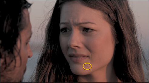
For example, in the clip below we will use the Surface Tracker to remove a small mole from the woman’s chin. Normally, we could use a Patch Replacer FX to put a smooth area of skin nearby over the mole. This shot is tricky to use effectively in the Patch Replacer because the subject cocks her head while she’s talking, as the camera trucks around her.
For example, in the clip below we will use the Surface Tracker to remove a small mole from the woman’s chin. Normally, we could use a Patch Replacer FX to put a smooth area of skin nearby over the mole. This shot is tricky to use effectively in the Patch Replacer because the subject cocks her head while she’s talking, as the camera trucks around her.
For example, in the clip below we will use the Surface Tracker to remove a small mole from the woman’s chin. Normally, we could use a Patch Replacer FX to put a smooth area of skin nearby over the mole. This shot is tricky to use effectively in the Patch Replacer because the subject cocks her head while she’s talking, as the camera trucks around her.
— Once your adjustments are finished, you then feed the RGB output of the corrector node back into an exact copy of the first Surface Tracker node. The copied Surface Tracker node’s Output then needs to be set to Rewarp Stabilized Clip instead. This re-lays the adjusted mesh back on to the original video clip. Directly copying an FX node like the Surface Tracker is not currently supported. To copy the Surface Tracker, you must grab a still into your Gallery, then right-click on it and append the still’s node graph back into your same clip, deleting the excess duplicate nodes other than the Surface Tracker.

This movement on all axes means that the area of skin underneath the source patch is changing angle and lighting all the time, ruining the effect. While the patch replacer does support tracking, the mole is on her chin and her talking also causes the skin around her cheek to deform, making it unsuitable for a simple track.
In this case, we can use the Surface Tracker’s Stabilize Warp function to “hold” those face area pixels in place under the source and target patches, patch them, and then make a Rewarp Stabilized Clip version of the Surface Tracker to lay those corrected pixels back onto the original image.
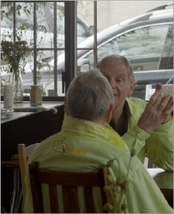
We want to remove this mole from the woman’s chin. Because of camera movement, combined with her chin and cheek deforming as she talks, this is difficult to achieve with the Patch Replacer alone.
![]()
First we will create a mesh on her face and track it as described above. Making holes for the eyes and mouth so their rapid movement does not disturb the mesh on her face.
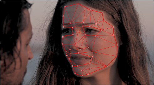
We apply the mesh to her face and track it, leaving holes in the mesh for her eyes and mouth.
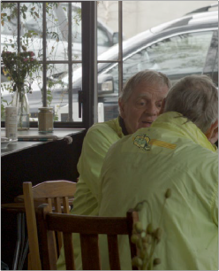
Once the tracking is complete, in Result we will choose the Output mode Stabilize-Warp Input 1. This will freeze the mesh in place and give us the resulting output, which we will feed into a Patch Replacer node. Now we can simply use the Patch replacer statically to hide the mole using another area of skin. No tracking is required. Because the mesh is static, and the video warps within it, this area now perfectly matches the angles, lighting changes, and skin stretching of the area as she talks.
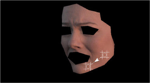
The frozen mesh stays in place (the face) and the video warps inside it. This allows us to use a static Patch Replacer to replace the mole area, with a smooth area on her cheek. No additional tracking is required.
![]()
At this point, we will then make an exact copy the Surface Tracker node, and place it after the Patch Replacer. To copy the Surface Tracker node, we must grab a still of the current clip, and then right-click on the still in the Gallery and select Append Node Graph to duplicate it back into our node tree. We want to delete any excess nodes added, and keep only the copy of the Surface Tracker. Then in the copied Surface Tracker, we need to select “Rewarp Stabilized Clip” from the Result tab’s Output mode. Then connect the original clip to RGB input 1, and the output from the Patch Replacer to RGB input 2, as shown in the node graph below:
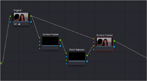
The node tree showing the correct setup for Warp Stabilizing the mesh. The first Surface Tracker node has its Result Output set to “Stabilize-Warp Input 1.” The second copy of the Surface Tracker node has its Result Output set to “Rewarp Stabilized Clip.” The actual mole removal will take place in the Patch Replacer FX node.