< Previous | Contents | Next >
Fairlight Console Audio Editor
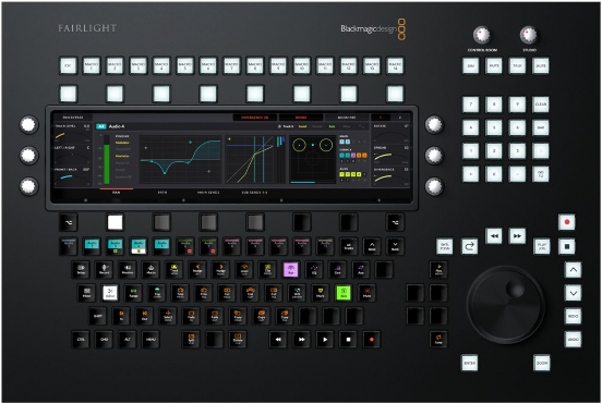
The legendary Fairlight Console Audio Editor lets you quickly navigate large projects and precisely edit audio much faster than using a regular mouse and keyboard. The Fairlight Console Audio Editor has an identical feature set and controls as the Fairlight Desktop Audio Editor. The difference is that the Console Audio Editor is connected to all the console’s control panels, so recording, playback, and editing functions are reflected on the corresponding channel bays and vise versa. For example, if a track is called in the Fader Panel, it is also loaded in the Audio Editor’s built-in display. Another example is if a track button is selected in the Audio Editor, the track is also selected in the Fairlight Page interface on the Editing LCD monitor, and the corresponding selection button shows active in
the In-Line Channel Control Extension buttons as well as the Channel Control LCD monitor. A Fairlight Desktop Audio Editor can also be connected to a Fairlight console that does not include an Audio Editing bay.
For details on the Fairlight Console Audio Editor’s features and functions, see Chapter 181, “ Using the Fairlight Desktop Console.”
Fairlight Console Audio Editor
![]()
Although the three channel bay components are separate modules, they work together in tandem as a single multifaceted unit to display and control various channel parameters. The Channel Fader panel offers traditional channel mixing controls, while the multi functional Channel Control panel focuses on controlling specific parameters as needed as well as how they are displayed on the Channel
LCD monitor.
Channel Control Modes
Within a Fairlight channel bay, the Channel Control panel works in three distinct channel control modes. These modes, in turn, change the functions of the multipurpose channel control knobs and buttons as well as the corresponding display in the LCD module:
Insert Safe Insert Safe Insert Safe Insert Safe Insert Safe Insert Safe Insert Safe Insert Safe Insert Safe Insert Safe Insert Safe Insert Safe Select Rec Select Rec Select Rec Select Rec Select Rec Select Rec Select Rec Select Rec Select Rec Select Rec Select Rec Select Rec Eq Comp Eq Comp Eq Comp Eq Comp Eq Comp Eq Comp Eq Comp Eq Comp Eq Comp Eq Comp Eq Comp Eq Comp | ||
CRL CRL MSTR PAN U1 PATH PLUG EQ U2 FLIT CHAN AUX U3 AUX ENAB COMP COPY U1 LIM CURVE U2 EXP SPILL U3 ALT ALT | ||
SOLO SOLO SOLO SOLO SOLO SOLO SOLO SOLO SOLO SOLO SOLO SOLO MUTE MUTE MUTE MUTE MUTE MUTE MUTE MUTE MUTE MUTE MUTE MUTE CALL AUTO CALL AUTO CALL AUTO CALL AUTO CALL AUTO CALL AUTO CALL AUTO CALL AUTO CALL AUTO CALL AUTO CALL AUTO CALL AUTO CRL BANK FLIP 1 POT 2 FDR 3 MAP 4 BUS 5 MSET 6 LOCK | ||
![]()
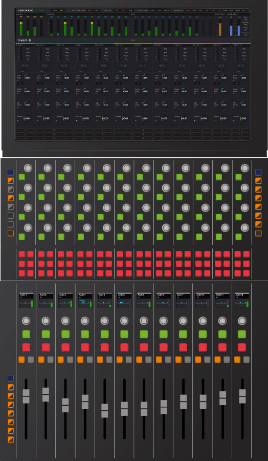
Channel Control components set to In-Line mode
— In-line: This mode effectively separates the knobs and buttons on the channel control module into 12 groups that line up vertically with the 12 faders on the channel fader control. As the name suggests, in-line mode shows each set of parameters in a line that continues from the fader channels up through the channel controls and into the display on the LCD monitor. In-line Display buttons on the right side of the Channel Control panel determine which in-line parameters are shown. This mode is common in live recording so that the operator can easily see and control parameters of multiple microphone inputs simultaneously.
Insert Safe Insert Safe Insert Safe Insert Safe Insert Safe Insert Safe Insert Safe Insert Safe Insert Safe Insert Safe Insert Safe Insert Safe Select Rec Select Rec Select Rec Select Rec Select Rec Select Rec Select Rec Select Rec Select Rec Select Rec Select Rec Select Rec Eq Comp Eq Comp Eq Comp Eq Comp Eq Comp Eq Comp Eq Comp Eq Comp Eq Comp Eq Comp Eq Comp Eq Comp |
CRL CRL MSTR PAN U1 PATH PLUG EQ U2 FLIT CHAN AUX U3 AUX ENAB COMP COPY U1 LIM CURVE U2 EXP SPILL U3 ALT ALT |
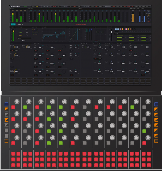
Channel Control components in Channel mode
![]()
— Channel: Use Channel mode to control up to 192 parameters on one channel. In channel mode, the 12 groups of controls on the channel control module are used collectively to adjust parameters for a specific channel from left to right as displayed on the LCD Monitor. In Channel mode, there are several ways to choose which channel is displayed, including the Channel Call buttons on the Channel Fader panel, the Channel Select buttons on Channel Control panel, the Call Follows menu, the edit controller, or by selecting a track in the Fairlight page Timeline or Mixer. This is the most common channel control mode in audio post production, as it provides quick access to all parameter controls for a specific track.
Insert Safe Insert Safe Insert Safe Insert Safe Insert Safe Insert Safe Insert Safe Insert Safe Insert Safe Insert Safe Insert Safe Insert Safe Select Rec Select Rec Select Rec Select Rec Select Rec Select Rec Select Rec Select Rec Select Rec Select Rec Select Rec Select Rec Eq Comp Eq Comp Eq Comp Eq Comp Eq Comp Eq Comp Eq Comp Eq Comp Eq Comp Eq Comp Eq Comp Eq Comp |
CTL CTL MSTR PAN U1 PATH PLUG EQ U2 FILT CHAN AUX U3 AUX ENAB COMP COPY U1 LIM CURVE U2 EXP SPLL U3 ALT ALT |
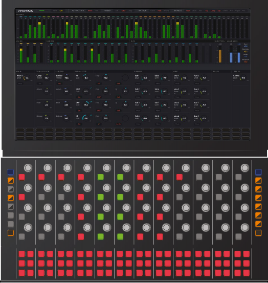
Channel Control components in Master mode
— Master: This mode utilizes all channel controls to adjust parameters for the buses and main output. In Master mode, the 12 groups of controls on the channel control panel adjust the adjacent main output parameters displayed on the LCD. The channel controls in Master mode are organized from left to right in order of processing. Master mode is commonly used while mixing and mastering soundtracks.