
< Previous | Contents | Next >
Fader Bank Display Buttons
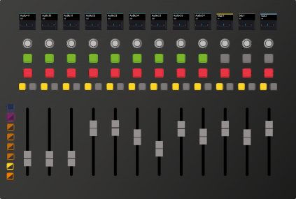
On the left side of the Channel Fader module are seven multicolored LED Bank Display buttons that are used to display, map, bus, set, and lock banks of channels to the 12 faders on the panel. The top two buttons are CTL (control) and BANK, which are modifier buttons used to access secondary button functions or additional fader banks for the subsequent numbered Fader Bank Display buttons.
Each of the six numbered Fader Bank Display buttons serve three functions, including load a primary fader bank, load an additional fader bank when pressed with the Bank modifier button, or perform
a secondary function when the Control button is pressed. You can easily identify the blue Control button at the top of the Fader Bank Display buttons, while the other seven buttons are yellow in their normal state, and blue or purple when the secondary function is selected via the Control button.

CTL | ||
10 • | • 10 | |
BANK | ||
FLIP | 5 • | • 5 |
1 | ||
POT | 0 • | • 0 |
2 | 5 • | • 5 |
FDR | ||
3 | 10 • | • 10 |
MAP | 15 • | • 15 |
20 • | • 20 | |
4 | 30 • | • 30 |
BUS | 40 • | • 40 |
5 | 50 • | • 50 |
MSET | 70 • | • 70 |
100 • | • 100 | |
6 | ||
LOCK |
CTL | ||
10 • | • 10 | |
BANK | ||
FLIP | 5 • | • 5 |
1 | ||
POT | 0 • | • 0 |
2 | 5 • | • 5 |
FDR | ||
3 | 10 • | • 10 |
MAP | 15 • | • 15 |
20 • | • 20 | |
4 | 30 • | • 30 |
BUS | 40 • | • 40 |
5 | 50 • | • 50 |
MSET | 70 • | • 70 |
100 • | • 100 | |
6 | ||
LOCK |
CTL | ||
10 • | • 10 | |
BANK | ||
FLIP | 5 • | • 5 |
1 | ||
POT | 0 • | • 0 |
2 | 5 • | • 5 |
FDR | ||
3 | 10 • | • 10 |
MAP | 15 • | • 15 |
20 • | • 20 | |
4 | 30 • | • 30 |
BUS | 40 • | • 40 |
5 | 50 • | • 50 |
MSET | 70 • | • 70 |
100 • | • 100 | |
6 | ||
LOCK |
CTL | ||
10 • | • 10 | |
BANK | ||
FLIP | 5 • | • 5 |
1 | ||
POT | 0 • | • 0 |
2 | 5 • | • 5 |
FDR | ||
3 | 10 • | • 10 |
MAP | 15 • | • 15 |
20 • | • 20 | |
4 | 30 • | • 30 |
BUS | 40 • | • 40 |
5 | 50 • | • 50 |
MSET | 70 • | • 70 |
100 • | • 100 | |
6 | ||
LOCK |
CTL | ||
10 • | • 10 | |
BANK | ||
FLIP | 5 • | • 5 |
1 | ||
POT | 0 • | • 0 |
2 | 5 • | • 5 |
FDR | ||
3 | 10 • | • 10 |
MAP | 15 • | • 15 |
20 • | • 20 | |
4 | 30 • | • 30 |
BUS | 40 • | • 40 |
5 | 50 • | • 50 |
MSET | 70 • | • 70 |
100 • | • 100 | |
6 | ||
LOCK |
CTL | ||
10 • | • 10 | |
BANK | ||
FLIP | 5 • | • 5 |
1 | ||
POT | 0 • | • 0 |
2 | 5 • | • 5 |
FDR | ||
3 | 10 • | • 10 |
MAP | 15 • | • 15 |
20 • | • 20 | |
4 | 30 • | • 30 |
BUS | 40 • | • 40 |
5 | 50 • | • 50 |
MSET | 70 • | • 70 |
100 • | • 100 | |
6 | ||
LOCK |
With the Fader Bank Display buttons, you can map each of the 12 fader banks with 12 different faders to control a total of 144 tracks and buses to the 12 faders. The more Fairlight Console Channel Fader panels you have in your console, the more faders and tracks you can control. For example, the Fairlight Console 5.bay, is designed for high-end mixing and mastering with four Fader Panels to control up to 576 channels and busses at a time.
![]()
Fader Bank display buttons and touch- sensitive fader with Bank 1 selected, and with the secondary button functions available while the Control button is pressed.
SOLO SOLO SOLO SOLO SOLO SOLO SOLO SOLO SOLO SOLO SOLO SOLO
MUTE MUTE MUTE MUTE MUTE MUTE MUTE MUTE MUTE MUTE MUTE MUTE
CALL AUTO CALL AUTO CALL AUTO CALL AUTO CALL AUTO CALL AUTO CALL AUTO CALL AUTO CALL AUTO CALL AUTO CALL AUTO CALL AUTO
BLUE
10 • • 10 10 • • 10 10 • • 10 10 • • 10 10 • • 10 10 • • 10 10 • • 10 10 • • 10 10 • • 10 10 • • 10 10 • • 10 10 • • 10
BANK
FLIP 5 • • 5 5 • • 5 5 • • 5 5 • • 5 5 • • 5 5 • • 5 5 • • 5 5 • • 5 5 • • 5 5 • • 5 5 • • 5 5 • • 5
1
POT 0 • • 0 0 • • 0 0 • • 0 0 • • 0 0 • • 0 0 • • 0 0 • • 0 0 • • 0 0 • • 0 0 • • 0 0 • • 0 0 • • 0
2 5 • • 5 5 • • 5 5 • • 5 5 • • 5 5 • • 5 5 • • 5 5 • • 5 5 • • 5 5 • • 5 5 • • 5 5 • • 5 5 • • 5
FDR
3 10 • • 10 10 • • 10 10 • • 10 10 • • 10 10 • • 10 10 • • 10 10 • • 10 10 • • 10 10 • • 10 10 • • 10 10 • • 10 10 • • 10
MAP 15 • • 15 15 • • 15 15 • • 15 15 • • 15 15 • • 15 15 • • 15 15 • • 15 15 • • 15 15 • • 15 15 • • 15 15 • • 15 15 • • 15
20 • • 20 20 • • 20 20 • • 20 20 • • 20 20 • • 20 20 • • 20 20 • • 20 20 • • 20 20 • • 20 20 • • 20 20 • • 20 20 • • 20
4 30 • • 30 30 • • 30 30 • • 30 30 • • 30 30 • • 30 30 • • 30 30 • • 30 30 • • 30 30 • • 30 30 • • 30 30 • • 30 30 • • 30
BUS
40 • • 40 40 • • 40 40 • • 40 40 • • 40 40 • • 40 40 • • 40 40 • • 40 40 • • 40 40 • • 40 40 • • 40 40 • • 40 40 • • 40
5 50 • • 50 50 • • 50 50 • • 50 50 • • 50 50 • • 50 50 • • 50 50 • • 50 50 • • 50 50 • • 50 50 • • 50 50 • • 50 50 • • 50
MSET 70 • • 70 70 • • 70 70 • • 70 70 • • 70 70 • • 70 70 • • 70 70 • • 70 70 • • 70 70 • • 70 70 • • 70 70 • • 70 70 • • 70
100 • • 100 100 • • 100 100 • • 100 100 • • 100 100 • • 100 100 • • 100 100 • • 100 100 • • 100 100 • • 100 100 • • 100 100 • • 100 100 • • 100
6
LOCK
Fader Bank Display buttons
![]()
![]()
![]()
![]()
![]()
![]()
![]()
![]()

NOTE: You can temporarily isolate faders from banking by actively touching and holding an individual fader or group of faders while changing fader banks. These “Sticky” faders will be cleared from isolation when the user changes fader banks without holding the fader.
NOTE: You can temporarily isolate faders from banking by actively touching and holding an individual fader or group of faders while changing fader banks. These “Sticky” faders will be cleared from isolation when the user changes fader banks without holding the fader.
NOTE: You can temporarily isolate faders from banking by actively touching and holding an individual fader or group of faders while changing fader banks. These “Sticky” faders will be cleared from isolation when the user changes fader banks without holding the fader.
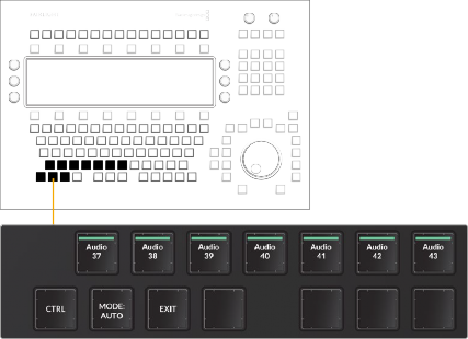
1 In the Fader Bank Display buttons, press CTRL and the 3/Map key to enter fader mapping mode. You’ll know that you entered bank mapping mode because all of the Call buttons turn red. The bank mapping is set to Auto mode by default, which automatically maps channels to faders in sequential order in groups of 12 up to 144. When you enter channel mapping mode, the top four rows of picture keys in the Audio Editor change to track selection keys, while the bottom row of picture keys shows the following dedicated channel mapping function keys:
— Exit: Exits the channel mapping mode.
— Delete: Deletes the channel assigned to the active channel indicated by the tallied red Call button.
— Blank: Leaves a blank fader bank beneath the active red Call button. This is useful for
adding a space between groups of similar tracks such as dialogue, background sound effects, and music.
— Insert: As the name suggests, this key inserts an unassigned fader in the position of the active red Call button.
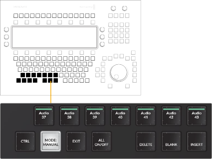
2 In the bottom row of the picture keyboard, press the first key (MODE:Auto/MODE:Manual) to toggle the fader mapping to Manual mode.
3 Press the red Call button on the fader you would like to assign, then choose a channel from the track selection buttons on the adjacent picture keys in the Audio Editor. Once you assign a track or bus to a fader, the next fader to the right becomes active with a red tallied Call button so that you can continue assigning faders sequentially. This automatic call selection also applies to the Delete, Blank, and Insert manual mapping functions.
4 Select up to 12 track selection keys to assign to the current fader bank. Use the Bank display buttons to manually assign additional banks as needed.
5 When you are finished mapping tracks to faders, press the Exit button in the bottom row of picture keys. Once you exit manual mapping mode, the picture keyboard layout returns to the current mode.
Example of Fader Bank 1 in Auto Mapping Mode
CRL BANK FLIP 1 POT 2 FDR 3 MAP 4 BUS 5 MSET 6 LOCK | SOLO MUTE CALL AUTO | SOLO MUTE CALL AUTO | SOLO MUTE CALL AUTO | SOLO MUTE CALL AUTO | SOLO MUTE CALL AUTO | SOLO MUTE CALL AUTO | SOLO MUTE CALL AUTO | SOLO MUTE CALL AUTO | SOLO MUTE CALL AUTO | SOLO MUTE CALL AUTO | SOLO MUTE CALL AUTO | SOLO MUTE CALL AUTO |
CRL BANK FLIP 1 POT 2 FDR 3 MAP 4 BUS 5 MSET 6 LOCK | SOLO MUTE CALL AUTO | SOLO MUTE CALL AUTO | SOLO MUTE CALL AUTO | SOLO MUTE CALL AUTO | SOLO MUTE CALL AUTO | SOLO MUTE CALL AUTO | SOLO MUTE CALL AUTO | SOLO MUTE CALL AUTO | SOLO MUTE CALL AUTO | SOLO MUTE CALL AUTO | SOLO MUTE CALL AUTO | SOLO MUTE CALL AUTO |
CRL BANK FLIP 1 POT 2 FDR 3 MAP 4 BUS 5 MSET 6 LOCK | SOLO MUTE CALL AUTO | SOLO MUTE CALL AUTO | SOLO MUTE CALL AUTO | SOLO MUTE CALL AUTO | SOLO MUTE CALL AUTO | SOLO MUTE CALL AUTO | SOLO MUTE CALL AUTO | SOLO MUTE CALL AUTO | SOLO MUTE CALL AUTO | SOLO MUTE CALL AUTO | SOLO MUTE CALL AUTO | SOLO MUTE CALL AUTO |
Fader Bank 1 in Auto mapping mode showing sequential tracks 1-12
Fader Bank 1 in Auto mapping mode showing sequential tracks 1-12 with
red Call buttons to indicate bank mapping mode is engaged and the
first fader channel’s Call button is active
Picture keyboard in Auto Fader Bank mapping mode
Auto Fader Bank mapping action keys in the lower left corner of the picture keyboard
SOLO
SOLO
SOLO
SOLO
SOLO
SOLO
SOLO
SOLO
SOLO
SOLO
SOLO
SOLO
SOLO
SOLO
SOLO
SOLO
SOLO
SOLO
SOLO
SOLO
SOLO
SOLO
SOLO
SOLO
SOLO
SOLO
SOLO
SOLO
SOLO
SOLO
SOLO
SOLO
SOLO
SOLO
SOLO
SOLO
MUTE
MUTE
MUTE
MUTE
MUTE
MUTE
MUTE
MUTE
MUTE
MUTE
MUTE
MUTE
MUTE
MUTE
MUTE
MUTE
MUTE
MUTE
MUTE
MUTE
MUTE
MUTE
MUTE
MUTE
MUTE
MUTE
MUTE
MUTE
MUTE
MUTE
MUTE
MUTE
MUTE
MUTE
MUTE
MUTE
CALL AUTO CALL AUTO CALL AUTO CALL AUTO CALL AUTO CALL AUTO CALL AUTO CALL AUTO CALL AUTO CALL AUTO CALL AUTO CALL AUTO
CALL AUTO CALL AUTO CALL AUTO CALL AUTO CALL AUTO CALL AUTO CALL AUTO CALL AUTO CALL AUTO CALL AUTO CALL AUTO CALL AUTO
CALL AUTO CALL AUTO CALL AUTO CALL AUTO CALL AUTO CALL AUTO CALL AUTO CALL AUTO CALL AUTO CALL AUTO CALL AUTO CALL AUTO
CRL
BANK FLIP
CRL
BANK FLIP
CRL
BANK FLIP
1
1
1
POT
POT
POT
2
2
2
FDR
FDR
FDR
3
3
3
MAP
MAP
MAP
4
4
4
BUS
BUS
BUS
5
5
5
MSET
MSET
MSET
6
6
6
LOCK
LOCK
LOCK
Example of Fader Bank 1 in Manual Mapping Mode
Manual Fader Bank mapping action keys in the bottom row of the picture keyboard
Fader Bank 1 in Manual mapping mode showing the custom mapping:
A21, blank, A30, A40,
and DIALOG to the first five tracks
Fader Bank 1 in Manual mapping mode showing custom mapping:
A21, blank, A30, A40,
and DIALOG mapped to the first five faders; red Call buttons indicate bank mapping is engaged, with
![]()
the first fader’s Call button active
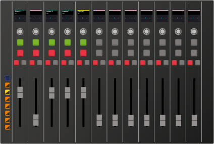
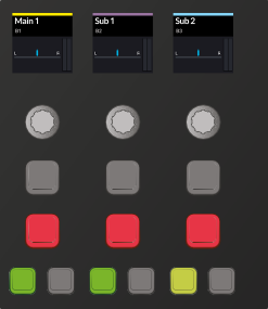
1 In the Fader Bank Display buttons, select a fader bank that contains at least one bus. Buses include main, submix, Aux buses, and VCA groups.
2 Momentarily press and hold the Bank/Flip key to change the yellow Call buttons to green Call buttons on the bus fader channels.
3 Press the green Call button for the bus fader you wish to spill to the neighboring faders. Once spilled, the Bank/Flip button turns purple to indicate that the current fader bank is displaying spilled faders for the active bus.
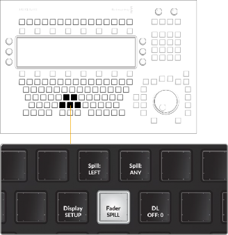
4 To modify the fader spill direction or type of fader that is temporarily remapped, use the Fader Spill options keys available in the Setup mode picture key toolset.
— Fader Spill: Use this menu key to reveal two menu Spill option keys that determine the type of fader channel and direction in which member tracks are temporarily mapped to the adjoining faders on the Fairlight Channel Fader panel.
— Spill Left/Spill Right: This menu options key toggles between Spill:Left and Spill:Right, which in turn dictates whether the member tracks of a bus are assigned to neighboring faders to the left or right of a bus when Spill is engaged in the Channel Fader panel.
— Spill Any/Spill Tracks: When in the default (unlatched) state the Spill:Any menu option allows member tracks of a bus to be spilled to the nearest faders to the left or right, including faders assigned to Master buses and VCA groups. When latched to the Spill:Tracks option, member tracks of a bus spill either left or right starting with the nearest track fader in the designated direction. This option is useful if you need to maintain fader control of your buses while you spill their constituent tracks to the nearest track faders.
![]()
Fader Spill and Fader Spill option keys available in Setup Mode toolset on the Audio Editor Picture keys
SOLO
SOLO
SOLO
SOLO
SOLO
SOLO
SOLO
SOLO
SOLO
SOLO
SOLO
SOLO
SOLO
SOLO
SOLO
SOLO
SOLO
SOLO
SOLO
SOLO
SOLO
SOLO
SOLO
SOLO
SOLO
SOLO
SOLO
SOLO
SOLO
SOLO
SOLO
SOLO
SOLO
SOLO
SOLO
SOLO
MUTE
MUTE
MUTE
MUTE
MUTE
MUTE
MUTE
MUTE
MUTE
MUTE
MUTE
MUTE
MUTE
MUTE
MUTE
MUTE
MUTE
MUTE
MUTE
MUTE
MUTE
MUTE
MUTE
MUTE
MUTE
MUTE
MUTE
MUTE
MUTE
MUTE
MUTE
MUTE
MUTE
MUTE
MUTE
MUTE
CALL AUTO
CALL AUTO
CALL AUTO
CALL AUTO
CALL AUTO
CALL AUTO
CALL AUTO
CALL AUTO
CALL AUTO
CALL AUTO
CALL AUTO
CALL AUTO
CALL AUTO
CALL AUTO
CALL AUTO
CALL AUTO
CALL AUTO
CALL AUTO
CALL AUTO
CALL AUTO
CALL AUTO
CALL AUTO
CALL AUTO
CALL AUTO
CALL AUTO
CALL AUTO
CALL AUTO
CALL AUTO
CALL AUTO
CALL AUTO
CALL AUTO
CALL AUTO
CALL AUTO
CALL AUTO
CALL AUTO
CALL AUTO
CRL
BANK FLIP
1
POT
2
FDR
3
MAP
4
BUS
5
MSET
6
LOCK
CRL
BANK FLIP
1
POT
2
FDR
3
MAP
4
BUS
5
MSET
6
LOCK
CRL
BANK FLIP
1
POT
2
FDR
3
MAP
4
BUS
5
MSET
6
LOCK
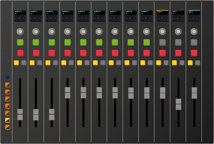
Fader Bank 5 with Main 1, Sub 1, and Sub 2 buses assigned to the last three faders; yellow Call buttons indicate standard channel bank display
SOLO
SOLO
SOLO
SOLO
SOLO
SOLO
SOLO
SOLO
SOLO
SOLO
SOLO
SOLO
SOLO
SOLO
SOLO
SOLO
SOLO
SOLO
SOLO
SOLO
SOLO
SOLO
SOLO
SOLO
SOLO
SOLO
SOLO
SOLO
SOLO
SOLO
SOLO
SOLO
SOLO
SOLO
SOLO
SOLO
MUTE
MUTE
MUTE
MUTE
MUTE
MUTE
MUTE
MUTE
MUTE
MUTE
MUTE
MUTE
MUTE
MUTE
MUTE
MUTE
MUTE
MUTE
MUTE
MUTE
MUTE
MUTE
MUTE
MUTE
MUTE
MUTE
MUTE
MUTE
MUTE
MUTE
MUTE
MUTE
MUTE
MUTE
MUTE
MUTE
CALL AUTO
CALL AUTO
CALL AUTO
CALL AUTO
CALL AUTO
CALL AUTO
CALL AUTO
CALL AUTO
CALL AUTO
CALL AUTO
CALL AUTO
CALL AUTO
CALL AUTO
CALL AUTO
CALL AUTO
CALL AUTO
CALL AUTO
CALL AUTO
CALL AUTO
CALL AUTO
CALL AUTO
CALL AUTO
CALL AUTO
CALL AUTO
CALL AUTO
CALL AUTO
CALL AUTO
CALL AUTO
CALL AUTO
CALL AUTO
CALL AUTO
CALL AUTO
CALL AUTO
CALL AUTO
CALL AUTO
CALL AUTO
CRL
BANK FLIP
1
POT
2
FDR
3
MAP
4
BUS
5
MSET
6
LOCK
CRL
BANK FLIP
1
POT
2
FDR
3
MAP
4
BUS
5
MSET
6
LOCK
CRL
BANK FLIP
1
POT
2
FDR
3
MAP
4
BUS
5
MSET
6
LOCK
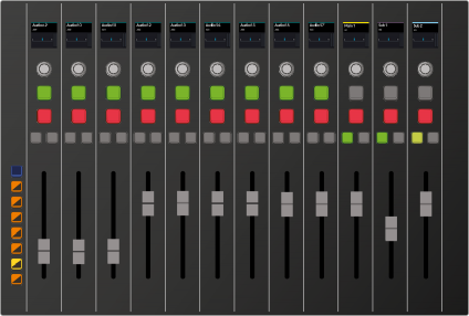
Bank/Flip Bank Display Button momentarily held to display the buses
within the active track; these buses (in the right 3 channels) can be easily identified by the green Call buttons
![]()
Channel LCD displays Sub 2 bus, including A8, A10, A11, and
A12, spilled on the nearest tracks to the left of the Sub 2 bus

NOTE: While a bus fader is spilled, you may still use the standard bank display buttons to display any of the other banks normally.
NOTE: While a bus fader is spilled, you may still use the standard bank display buttons to display any of the other banks normally.
NOTE: While a bus fader is spilled, you may still use the standard bank display buttons to display any of the other banks normally.
CRL BANK FLIP 1 POT 2 FDR 3 MAP 4 BUS 5 MSET 6 LOCK | SOLO MUTE CALL AUTO | SOLO MUTE CALL AUTO | SOLO MUTE CALL AUTO | SOLO MUTE CALL AUTO | SOLO MUTE CALL AUTO | SOLO MUTE CALL AUTO | SOLO MUTE CALL AUTO | SOLO MUTE CALL AUTO | SOLO MUTE CALL AUTO | SOLO MUTE CALL AUTO | SOLO MUTE CALL AUTO | SOLO MUTE CALL AUTO |
CRL BANK FLIP 1 POT 2 FDR 3 MAP 4 BUS 5 MSET 6 LOCK | SOLO MUTE CALL AUTO | SOLO MUTE CALL AUTO | SOLO MUTE CALL AUTO | SOLO MUTE CALL AUTO | SOLO MUTE CALL AUTO | SOLO MUTE CALL AUTO | SOLO MUTE CALL AUTO | SOLO MUTE CALL AUTO | SOLO MUTE CALL AUTO | SOLO MUTE CALL AUTO | SOLO MUTE CALL AUTO | SOLO MUTE CALL AUTO |
CRL BANK FLIP 1 POT 2 FDR 3 MAP 4 BUS 5 MSET 6 LOCK | SOLO MUTE CALL AUTO | SOLO MUTE CALL AUTO | SOLO MUTE CALL AUTO | SOLO MUTE CALL AUTO | SOLO MUTE CALL AUTO | SOLO MUTE CALL AUTO | SOLO MUTE CALL AUTO | SOLO MUTE CALL AUTO | SOLO MUTE CALL AUTO | SOLO MUTE CALL AUTO | SOLO MUTE CALL AUTO | SOLO MUTE CALL AUTO |
Purple Bank/Flip button indicates there is a spilled bus in the current bank. In this case, Bank 5 is showing, with Sub 2 spilled to the left of the the other buses, and includes A8, A10, A11, and A12 as the member tracks that comprise Sub 2.
1 In the Fader Bank Display buttons, press the Bank button that contains the spilled bus.
2 Momentarily hold the Bank/Flip button to reveal green Call buttons for the bus faders. The spilled fader’s green Call button will be tallied on.

NOTE: You can only spill bus member tracks to faders within the same fader bank. Use the Fader Spill option keys in the Audio Editor Setup mode toolset to spill either left or right within the current bank of 12 faders. Additionally, if you press the Bank/Flip button on a bank without any bus faders, you will not see any green Call buttons or subsequent bus faders to spill.
NOTE: You can only spill bus member tracks to faders within the same fader bank. Use the Fader Spill option keys in the Audio Editor Setup mode toolset to spill either left or right within the current bank of 12 faders. Additionally, if you press the Bank/Flip button on a bank without any bus faders, you will not see any green Call buttons or subsequent bus faders to spill.
NOTE: You can only spill bus member tracks to faders within the same fader bank. Use the Fader Spill option keys in the Audio Editor Setup mode toolset to spill either left or right within the current bank of 12 faders. Additionally, if you press the Bank/Flip button on a bank without any bus faders, you will not see any green Call buttons or subsequent bus faders to spill.
3 Press the active green Call button to un-spill the fader.
![]()
SOLO MUTE CALL AUTO | SOLO MUTE CALL AUTO | SOLO MUTE CALL AUTO |
SOLO MUTE CALL AUTO | SOLO MUTE CALL AUTO | SOLO MUTE CALL AUTO |
SOLO MUTE CALL AUTO | SOLO MUTE CALL AUTO | SOLO MUTE CALL AUTO |
Sub 2 bus with active (tallied) green Call button, which indicates it has been spilled to neighboring faders