< Previous | Contents | Next >
The Polygon node
Polygon Mask Node Introduction
The Polygon mask is most useful for masking objects that do not have a regular shape. When first added to a node, the Polygon mask consists of only Center and Angle controls, which are visible onscreen. Points are added to the polyline by clicking in the viewer. Each new point is connected to the last one created.
Like the B-Spline mask tool, the Polygon mask auto-animates. Adding this node to the Node Editor adds a keyframe to the current frame. Moving to a new frame and changing the shape creates a new keyframe and interpolate between the two defined shapes.
Inputs
The Polygon mask node includes a single effect mask input.
— Effect Mask: The optional blue input expects a mask shape created by polylines, basic primitive shapes, paint strokes, or bitmaps masks. Connecting a mask to this input combines the masks. How masks are combined is handled in the Paint mode menu in the Inspector.
![]()
Basic Node Setup
The Polygon node can be used to generate a detailed spline shape or combined with other masks for even more complex shapes. In the node tree below, the Polygon mask is used to generate detailed shape as a solid matte on the Delta Keyer.
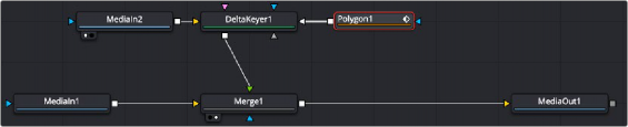
A Polygon node generates a detailed shape as a Solid matte.
Inspector
Polygon Mask controls
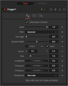
Controls Tab
The Controls tab is used to refine how the polyline appears after drawing it in the viewer.
The Show View Controls checkbox is used to enable/disable the display of the mask’s onscreen controls in the viewer. Onscreen controls, including center position, polylines, angles, and others, do not appear when this checkbox is disabled, even when the node is selected.
![]()

NOTE: Lowering the level of a mask lowers the values of all pixels covered by the mask in the mask channel. For example, if a Circle mask is placed over a Rectangle mask, lowering the level of the Circle mask lowers the values of all of the pixels in the mask channel, even though the Rectangle mask beneath it is still opaque.
NOTE: Lowering the level of a mask lowers the values of all pixels covered by the mask in the mask channel. For example, if a Circle mask is placed over a Rectangle mask, lowering the level of the Circle mask lowers the values of all of the pixels in the mask channel, even though the Rectangle mask beneath it is still opaque.
NOTE: Lowering the level of a mask lowers the values of all pixels covered by the mask in the mask channel. For example, if a Circle mask is placed over a Rectangle mask, lowering the level of the Circle mask lowers the values of all of the pixels in the mask channel, even though the Rectangle mask beneath it is still opaque.
The Level control sets the transparency level of the pixels in the mask channel. When the value is 1.0, the mask is completely opaque (unless it has a soft edge). Lower values cause the mask to be partially transparent. The result is identical to lowering the blend control of an effect.
This control selects the filtering algorithm used when applying Soft Edge to the mask.
— Box: This is the fastest method but at reduced quality. Box is best suited for minimal amounts of blur.
— Bartlett: Otherwise known as a Pyramid filter, Bartlett makes a good compromise between speed and quality.
— Multi-box: When selecting this filter, the Num Passes slider appears and lets you control the quality. At 1 and 2 passes, results are identical to Box and Bartlett, respectively. At 4 passes and above, results are usually as good as Gaussian, in less time and with no edge “ringing.”
— Gaussian: The Gaussian filter uses a true Gaussian approximation and gives excellent results, but it is a little slower than the other filters. In some cases, it can produce an extremely slight edge “ringing” on floating-point pixels.
Use the Soft Edge slider to blur (feather) the mask, using the selected filter. Higher values cause the edge to fade off well beyond the boundaries of the mask. A value of 0.0 creates a crisp, well- defined edge.
The Border Width control adjusts the thickness of the mask’s edge. When the solid checkbox is toggled on, the border thickens or narrows the mask. When the mask is not solid, the mask shape draws as an outline, and the width uses the Border Width setting.
Connecting a mask to the effect mask input displays the Paint mode menu. The Paint mode is used to determine how the incoming mask for the effect mask input and the mask created in the node are combined.
— Merge: Merge is the default for all masks. The new mask is merged with the input mask.
— Add: The mask’s values add to the input mask’s values.
— Subtract: In the intersecting areas, the new mask values subtract from the input mask’s values.
— Minimum: Comparing the input mask’s values and the new mask, this displays the lowest (minimum) value.
![]()
— Maximum: Comparing the input mask’s values and the new mask, this displays the highest (maximum) value.
— Average: This calculates the average (half the sum) of the new mask and the input mask.
— Multiply: This multiplies the values of the input mask by the new mask’s values.
— Replace: The new mask completely replaces the input mask wherever they intersect. Areas that are zero (completely black) in the new mask do not affect the input mask.
— Invert: Areas of the input mask that are covered by the new mask are inverted; white becomes black and vice versa. Gray areas in the new mask are partially inverted.
— Copy: This mode completely discards the input mask and uses the new mask for all values.
— Ignore: This mode completely discards the new mask and uses the input mask for all values.
Selecting this checkbox inverts the entire mask. Unlike the Invert Paint mode, the checkbox affects all pixels, regardless of whether the new mask covers them or not.
When the Solid checkbox is enabled, the mask is filled to be transparent (white) unless inverted. When disabled, the spline is drawn as just an outline whose thickness is determined by the Border Width slider.
These controls adjust the position of the polygon spline mask.
Use the Size control to adjust the scale of the polygon spline effect mask, without affecting the relative behavior of the points that compose the mask or setting a keyframe in the mask animation.
Use these three controls to adjust the rotation angle of the mask along any axis.
The Fill Method menu offers two different techniques for dealing with overlapping regions of a polyline. If overlapping segments in a mask are causing undesirable holes to appear, try switching the setting of this control from Alternate to Non Zero Winding.
By default, all polygon spline masks are animated when they are created. The initial keyframe is set to the current time, and any changes to the shape at different times create new keys.
Right-clicking on this label displays a contextual menu that offers options for removing or re-adding animation to the mask, or publishing and connecting the masks together.
Common Controls
The Image and Settings tabs in the Inspector are also duplicated in other mask nodes. These common controls are described in detail at the end of this chapter in “The Common Controls” section.
Adding Points
![]()
Adding Points to a polygonal effect mask is relatively simple. Immediately after adding the node to the Node Editor, there are no points, but the tool will be in Click Append mode. Click once in the viewer wherever a point is required for the mask. Continue clicking to draw the shape of the mask. When the shape is complete, click on the initial point again to close the mask.
When the shape is closed, the mode of the polyline will change to Insert and Modify. This allows for the adjusting and adding of additional points to the mask by clicking on segments of the polyline. To lock down the mask’s shape and prevent accidental changes, switch the Polyline mode to Done using the Polyline toolbar or contextual menu.
![]()
B-Spline Mask Polygon toolbar
When a Polygon (or B-Spline) mask is added to a node, a toolbar appears above the viewer, offering easy access to modes. Hold the pointer over any button in the toolbar to display a tooltip that describes that button’s function.
— Click: Click is the default option when creating a polyline (or B-Spline) mask. It is a Bézier style drawing tool. Clicking sets a control point and appends the next control point when you click again in a different location.
— Draw: Draw is a freehand drawing tool. It creates a mask similar to drawing with a pencil on paper. You can create a new mask using the Draw tool, or you can extend an existing open spline by clicking the Draw tool and starting to draw from the last control point.
— Insert: Insert adds a new control point along the spline.
— Modify: Modify allows you to safely move or smooth any exiting point along a spline without worrying about adding new points accidentally.
— Done: Prevents any point along the spline from being moved or modified. Also, new points cannot be added. You can, however, move and rotate the entire spline.
— Closed: Closes an open spline.
— Smooth: Changes the selected control point from a linear to a smooth curve.
— Linear: Changes the selected control point from a smooth curve to linear.
— Select All: Selects all the control points on the spline.
— Keys: Shows or hides the control points along the spline.
— Handles: Shows or hides the Bézier handles along the polyline.
— Shape: Places a reshape rectangle around the selected spline shape. Using the reshape rectangle, you can deform groups of control points or entire shapes much easier than modifying each point.
— Delete: Deletes the selected control point(s).
— Reduce: Opens a Freehand precision window that can be used to reduce the number of controls points on a spline. This can make the paint stroke easier to modify, especially if it has been created using the Draw tool.
— Publish menu: You can use the publish menu to select between publishing the control points or the path. Publishing is a form of parameter linking, it makes the selected item available for use by other controls. It also allows you to attach a control point to a tracker.
— Follow Points: Allows a selected point to follow the path of a published point. The point follows the published point using an offset position.
![]()
— Double Poly: Allows softening part of the spline curve while keeping other portions of the curve sharp. The double polyline is composed of two shapes, an inner and outer shape. The inner shape is the original shape from the single polyline, whereas the outer shape is used to determine the spread of the softness. The further the outer shape gets from the inner shape, the softer that segment of the shape becomes. Both polylines start with exactly the same shape as the original single polyline, keeping the mask sharp to start. Any animation already applied to the shape remains. To select the outer shape, press the Tab key to cycle between the onscreen controls until the dashed outline is visible, or you can select the outer polyline using the contextual menu’s Controls > Outer Polygon menu.
— Multiframe: Multiframe is a method of adjusting control points across multiple keyframes. The default setting of none only adjusts the control point of a spline on the current keyframe. Setting the menu to All adjusts the controls point for all keyframes. Prev settings adjust the current and previous keyframe while Next adjusts the current and next keyframe.
— Onion Skinning: Enabling onion skinning displays a mix in the viewer of the spline animation. It is useful when aligning spline animation and motion. Selecting Onion Skin Settings from the drop down menu allows you to set the number of overlapping frames.