< Previous | Contents | Next >
The Cineon Log node
Cineon Log Node Introduction
The Cineon Log node is used to convert several different log camera formats to linear gamma and back again. Although the name implies that it should be used with Cineon files, it handles “log” gamma from many different digital cinema sources such as Blackmagic Design, Arri, and Red cameras.
Input
There are two Inputs on the Cineon Log node: one for the log image and one for the effects mask.
— Input: The orange input is used for the primary 2D image that gets the highlight applied.
— Effect Mask: The blue input is for a mask shape created by polylines, basic primitive shapes, paint strokes, or bitmaps from other tools. Connecting a mask to this input restricts the log conversion to be within the pixels of the mask. An effects mask is applied to the tool after the tool is processed.
Basic Node Setup
![]()
The Cineon Log node is placed directly after a MediaIn node in DaVinci Resolve or a Loader node in Fusion Studio. It is also commonly placed before a MediaOut or Saver node to convert back to a Log- encoded image.
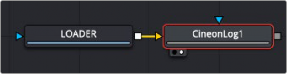
A Cineon Log node placed after a Loader node in Fusion Studio
Inspector
Cineon Log controls
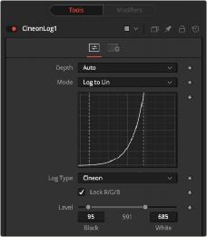
Controls Tab
The Controls tab includes settings for converting from log gamma to linear or from linear to log. You first select the Mode and then the Log Type. For instance, choose Log to Lin from the Mode menu, and then select BMD Film if you are compositing with a RAW clip from a Blackmagic Design camera. Those settings output a linear image ready for compositing.
The Depth menu is used to select the color depth used to process the input image. The default option is Auto. Auto determines the color depth based on the file format loaded. For example, JPEG files automatically process at 8 bit because the JPEG file format does not store color depths greater than
![]()
8. Blackmagic RAW files load at Float, etc. If the color depth of the format is undetermined, the default depth defined in the Frame Format preferences is used.
The Mode menu offers two options: one for converting log images to linear and one for converting linear images to logarithmic.
The Log Type menu allows you to select the source of the file. Typically, you select the camera used to create the image, although the Josh Pines option is specific to film scan workflows. This menu contains the following camera log types:
— Cineon
— Arri Log C
— BMD Film
— Canon Log
— Nikon N Log
— Panalog
— Panasonic V-Log
— Red Log Film
— Sony S-Log
— Viper Film Stream
— ACESlog
When enabled, the settings in this tab affect all color channels equally.
Disable this control to convert the red, green, and blue channels of the image using separate settings for each channel.
Use this range control to set the black level and white level in the log image before converting. The left handle adjusts the black level, while the right handle adjusts the white level. Pixels with values in log space below the black level become out-of-range values below 0.0. Pixels with values above the white level become out-of-range values above 1.0 after conversion.
When processing in floating-point color space, both negative and high out-of-range values are preserved. When using 16-bit or 8-bit mode, the out-of-range values are clipped.
The Soft Clip control is used to draw values that are out of range back into the image. This is done by smoothing the conversion curve at the top and bottom of the curve, allowing more values
to be represented.
Applying a soft clip of any value other than 1 causes the node to process at 16-bit integer, eliminating all out-of-range values that do not fit within the soft clip.
These controls are used to set the response curves of the logarithmic data during conversion. In addition to the settings above, a custom ASCII file Lookup Table (LUT) can be created with specific conversion values. The ASCII LUT file can be loaded using the Browse button.
Common Controls

Black Rolloff
Since a mathematical log() operation on a value of zero or lower results in invalid values, Fusion clips values below 1e-38 (0 followed by 38 zeros) to 0 to ensure correct results. This is almost never an issue, since values that small have no visual impact on an image. To see such tiny values, you would have to add three Brightness Contrast nodes, each with a gain set to 1,000,000. Even then, the values would hover very close to zero.
We have seen processes where instead of cropping these minimal values, they are instead scaled. So values between 0.0 and 1e-16 are scaled between 1e-18 and 1e-16. The idea is to crush the majority of the visual range in a float image into values very near to zero, then expand them again, forcing a gentle ramp to produce a small ramp in the extreme black values. Should you find yourself facing a color pipeline using this process, here is how you can mimic it with the help of a Custom node.
The process involves converting the log image to linear with a very small gamma and a wider than normal black level to white level (e.g., conversion gamma of 0.6, black of
10, white of 1010). This crushes most of the image’s range into very small values. This is followed by a Custom node (described below), and then by a linear to log conversion that reverses the process but uses a slightly higher black level. The difference between the black levels defines the falloff range.
![]()
The Settings tab controls are common to all Film nodes, so their descriptions can be found in “The Common Controls” section at the end of this chapter.
Since this lifts the blacks, the image is usually then converted back to linear one more time, using more traditional values (i.e., 95-685) to reset the black point.
The Custom node should use the following equation in the red, green, and blue expressions:
if (c1< 1e-16, 1e-18 + (c1/1e-16)*(1e-16 - 1e-18), c1)
Falloff Comparison
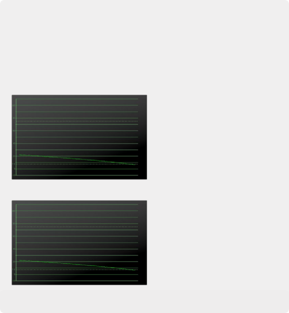
The black falloff from the native Fusion process
The black falloff from the native Fusion process
The black falloff from the native Fusion process
Virtually identical black falloff from the ramped clipping process
Virtually identical black falloff from the ramped clipping process
Virtually identical black falloff from the ramped clipping process
![]()