< Previous | Contents | Next >
The Settings tab controls are common to all Filter nodes, so their descriptions can be found in “The Common Controls” section at the end of this chapter.
Custom Filter Node [CFlt]
The Custom Filter node
Custom Filter Node Introduction
The Custom Filter node is used to apply custom convolution filters to images. A custom convolution filter can give a wide variety of image effects. For example, emboss, relief, sharpen, blurring, and edge detection are all convolution filters. There are many supplied custom filters in the Filters directory
that can be loaded by right-clicking on the control header and selecting Settings > Load from the contextual menu.
The Custom filter uses an array (or grid) of either 3 x 3, 5 x 5, or 7 x 7 values. (Note: The array in the Inspector always shows a 7 x 7 grid; however, setting the Matrix Size to 3 x 3 uses only the center 9 cells.) The center of the array represents the current pixel, and entries nearby represent adjacent
![]()
pixels. A value of 1 applies the full value of the pixel to the filter. A value of 0 ignores the pixel’s value. A value greater than 1 multiplies the pixel’s effect on the result. Negative values can also be entered, where the value of the pixel is subtracted from the average. Only integer values can be entered;
0.x is not valid.
Input
The Custom Filter node includes two inputs: one for the main image and the other for an effect mask to limit the area where the custom filter is applied.
— Input: The orange input takes the RGBA channels from an image to calculate the custom filter.
— Effect Mask: The optional blue effect mask input accepts a mask shape created by polylines, basic primitive shapes, paint strokes, or bitmaps from other tools. Connecting a mask to this input limits the custom filter to only those pixels within the mask. An effects mask is applied to the tool after the tool is processed.
Basic Node Setup
The Custom Filter node can be inserted after an image, mask, or any node that needs a custom convolution filter applied.
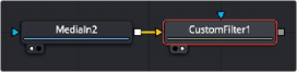
A Custom Filter node placed after a MediaIn node in DaVinci Resolve
Inspector
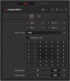
Custom Filter controls
Controls Tab
![]()
The Controls tab is used to set the filter size and then use the filter matrix to enter convolution filter values.
The custom filter defaults to operating on R, G, B, and A channels. Selective channel editing is possible by enabling or disabling the checkboxes beside each channel.
This is not the same as the RGBA checkboxes found under the Common Controls. The node takes these controls into account before it processes. Deselecting a channel causes the node to skip that channel when processing, speeding up the rendering of the effect. In contrast, these controls under the Common Controls tab are applied after the node has processed.
This menu is used to set the size of the filter at 3 x 3 pixels, 5 x 5 pixels, or 7 x 7 pixels, thus setting the radius of the pixels sampled. The larger the size, the more time it takes to render.
When this control is selected, Fusion does not render the filter. This is useful for setting up each value of the filter, and then turning off Update Lock and rendering the filter.
The Filter Matrix control is a 7 x 7 grid of text boxes where a number is entered to represent how much influence each pixel has on the overall convolution filter. The text box in the center represents the pixel that is processed by the filter. The text box to the left of the center represents the pixel to the immediate left, and so forth.
The default Matrix size is 3 x 3. Only the pixels immediately adjacent to the current pixel are analyzed. If a larger Matrix size is set, more of the text boxes in the grid are enabled for input.
This controls the amount of filter normalization that is applied to the result. Zero gives a normalized image. Positive values brighten or raise the level of the filter result. Negative values darken or lower the level.
This adds or subtracts a minimum, or Floor Level, to the result of the filtered image. Zero does not add anything to the image. Positive values add to the filtered image, and negative values subtract from
Examples
Original Image Example
For example, a filter with the values...
0 0 0
0 1 0
0 0 0
...has zero effect from its neighboring pixels, and the resulting image would be unchanged.
Examples
Original Image Example
For example, a filter with the values...
0 0 0
0 1 0
0 0 0
...has zero effect from its neighboring pixels, and the resulting image would be unchanged.
Examples
Original Image Example
For example, a filter with the values...
0 0 0
0 1 0
0 0 0
...has zero effect from its neighboring pixels, and the resulting image would be unchanged.
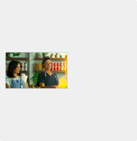
Original image
Original image
Original image
Softening Example
A slight softening effect would be...
1 1 1
1 1 1
1 1 1
Softening Example
A slight softening effect would be...
1 1 1
1 1 1
1 1 1
Softening Example
A slight softening effect would be...
1 1 1
1 1 1
1 1 1
![]()
the image.
...where the neighboring pixels are averaged with the center.
Before and after averaging neighboring pixels to soften the image
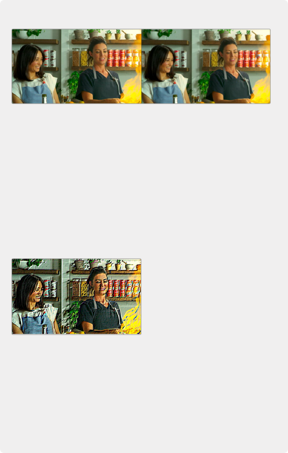
Emboss Example
The example below subtracts five times the value from the top left and adds five times the value from the lower right.
-5 0 0
0 1 0
0 0 5
If parts of the processed image are very smooth in color, the neighboring values are very similar.
In parts of the image where the pixels are different (e.g., an edge), the results are different and tend to highlight or emboss edges in the image.
![]()
A Custom Filter adding and subtracting neighboring pixels to create an embossed image
Exposure Example
Using the values...
1 1 1
1 1 1
1 1 1
...and adjusting Normalize to a positive value makes the image brighter or glow,
simulating film overexposure.
...and adjusting Normalize to a positive value makes the image brighter or glow,
simulating film overexposure.
...and adjusting Normalize to a positive value makes the image brighter or glow,
simulating film overexposure.
The Custom Filter Normalize slider used to change exposure
The Custom Filter Normalize slider used to change exposure
The Custom Filter Normalize slider used to change exposure
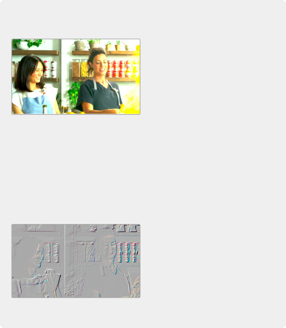
Relief Example
Using the values...
-1 0 0
0 0 0
0 0 1
... and adjusting Floor Level to a positive value creates a Relief filter.
Relief Example
Using the values...
-1 0 0
0 0 0
0 0 1
... and adjusting Floor Level to a positive value creates a Relief filter.
Relief Example
Using the values...
-1 0 0
0 0 0
0 0 1
... and adjusting Floor Level to a positive value creates a Relief filter.
Custom Filter Floor Level slider used to create a relief
Custom Filter Floor Level slider used to create a relief
Custom Filter Floor Level slider used to create a relief
![]()
Common Controls
The Settings tab controls are common to all Filter nodes, so their descriptions can be found in “The Common Controls” section at the end of this chapter.