< Previous | Contents | Next >
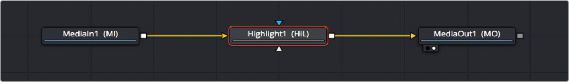
By default, MediaIn nodes in the Fusion page and Loader nodes in Fusion Studio output RGBA channels. When you connect one node’s output to another node’s input, the active channels are passed from the upstream node to the downstream node, which then processes the image according to that node’s function. Only one node output can be connected to a node input at a time. In this simple example, a MediaIn node’s output is connected to the input of a Highlight node to create a sparkly highlight effect.
MediaIn node connected to a Highlight node connected to MediaOut node in the Fusion page.
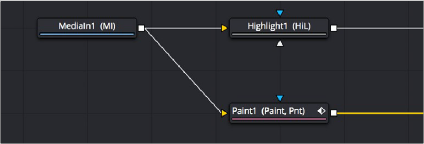
When connecting nodes, a node’s output carries the same channels no matter how many times the output is “branched.” You cannot send one channel out on one branch and a different channel out on another branch.
![]()
The MediaIn node’s output is branched but carries the same RGB channels to both inputs.
Using Multiple Inputs
Most nodes have two inputs, one for RGBA and another for an effect mask that can be optionally used to limit the effect of that node to a particular part of the image. However, some nodes have three or even more inputs, and it’s important to make sure you connect the correct image data to the appropriate input to obtain the desired result. If you connect one node’s output to another node’s input and nothing happens, chances are you’ve connected to the wrong input.
For example, the MatteControl node has a background input and a foreground input, both of which accept RGBA channels. However, it also has SolidMatte, GarbageMatte, and EffectsMask inputs
that accept alpha or mask channels to modify the transparency of the Node’s output. If you want to perform the extremely common operation of using a MatteControl node to create an alpha channel using a Polygon node for rotoscoping an image, you need to make sure that you connect the Polygon node to the GarbageMatte input to obtain the correct result. The GarbageMatte input is automatically set to alter the alpha channel of the foreground image. If you connect to any other input, your Polygon mask may not produce expected results.
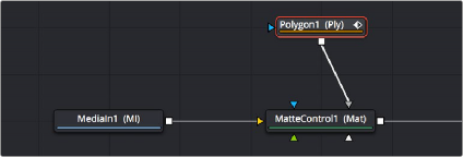
Polygon node connected to the GargabeMatte input of a MatteControl node for rotoscoping
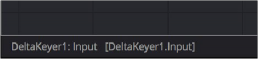
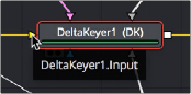
In another example, the DeltaKeyer node has a primary input (labeled “Input”) that accepts RGBA channels, but it also has three Matte inputs. These SolidMatte, GarbageMatte, and EffectsMask inputs on the Delta Keyer accept alpha or mask channels to modify the matte being extracted from the image in different ways.
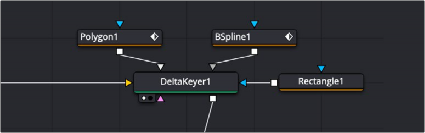
The DeltaKeyer combines the multiple mask nodes in different ways.
![]()
If you position your pointer over any node’s input or output, a tooltip appears in the Tooltip bar at the bottom of the Fusion window, letting you know what that input or output is for, to help guide you to using the right input for the job. If you pause for a moment longer, another tooltip appears in the Node Editor itself.
(Left) The node input’s tooltip in the Tooltip bar, (Right) The node tooltip in the Node Editor
Connecting to the Correct Input
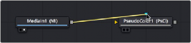
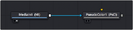
When you’re connecting nodes, pulling a connection line from the output of one node and dropping it right on top of the body of another node makes a connection to the default input for that node, which is typically the “Input” or “Background” input.
Side by side, dropping a connection on a node’s body to connect to that node’s primary input
However, if you drop a connection line right on top of a specific input, then you’ll connect to that input, so it’s important to be mindful of where you drop connection lines as you wire up different node
trees together.
Side by side, dropping a connection on a specific node input, note how the inputs rearrange themselves afterwards to keep the node tree tidy-looking

TIP: If you hold the Option key down while you drag a connection line from one node onto another, and you keep the Option key held down while you release the pointer’s button to drop the connection, a menu appears that lets you choose which specific input you want to connect to, by name.
TIP: If you hold the Option key down while you drag a connection line from one node onto another, and you keep the Option key held down while you release the pointer’s button to drop the connection, a menu appears that lets you choose which specific input you want to connect to, by name.
TIP: If you hold the Option key down while you drag a connection line from one node onto another, and you keep the Option key held down while you release the pointer’s button to drop the connection, a menu appears that lets you choose which specific input you want to connect to, by name.
Inputs Require Specific Channels
Usually, you’re prevented from connecting a node’s output to another node or node input that’s not compatible with it. For example, if you try to connect a Text3D node’s output directly to the input of a regular Merge node, it won’t work; 3D nodes do not produce RGB images, they produce 3D geometry data, so you must first connect to a Renderer3D node that creates the RGB output appropriate for 2D compositing operations.

TIP: This chapter tries to cover many of the easy-to-miss exceptions to node connection that are important for you to know, so don’t skim too fast.
TIP: This chapter tries to cover many of the easy-to-miss exceptions to node connection that are important for you to know, so don’t skim too fast.
TIP: This chapter tries to cover many of the easy-to-miss exceptions to node connection that are important for you to know, so don’t skim too fast.
![]()
In other cases, connecting the wrong image data to the wrong node input won’t give you any error, it simply fails to produce the result you were expecting, necessitating you to troubleshoot the composition. If this happens to you, check the Fusion Effects section of this manual to see if the node you’re trying to connect to has any limitations as to how it must be attached.
Always Connect the Background Input First
Many nodes combine images in different ways, using “background” and “foreground” inputs. This includes the Merge node, the Matte Control node, and the Channel Booleans node, to cite common examples. The color of inputs on a node can help you make the right corrections. For instance, background inputs are always orange, and foreground inputs are always green.
When you first connect any node’s output to a multi-input node, you usually want to connect the background input first. This is handled for you automatically when you first drop a connection line onto the body of a new multi-input node. The orange-colored background input is almost always connected first (the exception is Mask nodes, which always connect to the first available Mask input). This is good because you want to get into the habit of always connecting the background input first.

TIP: The only node to which you can safely connect the foreground input prior to the background input is the Dissolve node, which is a special node that can be used to either dissolve between two inputs, or automatically switch between two inputs of unequal duration.
TIP: The only node to which you can safely connect the foreground input prior to the background input is the Dissolve node, which is a special node that can be used to either dissolve between two inputs, or automatically switch between two inputs of unequal duration.
TIP: The only node to which you can safely connect the foreground input prior to the background input is the Dissolve node, which is a special node that can be used to either dissolve between two inputs, or automatically switch between two inputs of unequal duration.