< Previous | Contents | Next >
The 3D viewers and renderer use vertex lighting, meaning all lighting is calculated at the vertices on the 3D geometry and then interpolated from there. Therefore, the more subdivisions in the mesh, the more vertices are available to represent the lighting. For example, make a sphere and set the subdivisions to be small so it looks chunky. With lighting on, the object looks like a sphere but has
some amount of fracturing resulting from the large distance between vertices. When the subdivisions are high, the vertices are closer and the lighting becomes more even. So, increasing subdivisions can be useful when working interactively with lights.
Enabling the Cube Mapping checkbox causes the cube to wrap its first texture across all six faces using a standard cubic mapping technique. This approach expects a texture laid out in the shape of a cross.
Enabling this checkbox causes the mesh to render only the wireframe for the object when rendering with the OpenGL renderer in the Renderer 3D node.
Common Controls
The remaining controls for Visibility, Lighting, Matte, Blend Mode, Normals/Tangents, and Object ID are common to many 3D nodes. The same is true of the Materials, Transform, and Settings tabs. Their descriptions can be found in “The Common Controls” section at the end of this chapter.
Custom Vertex 3D [3CV]
![]()
The Custom Vertex 3D node
Custom Vertex 3D Node Introduction
The Custom Vertex 3D node is an advanced custom node for 3D geometry that performs per vertex manipulations. If you have moderate experience with scripting or C++ programming, you should find the structure and terminology used by the Custom node familiar.
Using scripting math functions and lookup tables from images, you can move vertex positions on 3D geometry. Vertices can be more than just positions in 3D space. You can manipulate normals, texture coordinates, vectors, and velocity.
For example, Custom Vertex 3D can be used to make a flat plane wave like a flag, or create spiral models.
Besides providing a 3D scene input and three image inputs, the Inspector includes up to eight number fields and as many as eight XYZ position values from other controls and parameters in the node tree.

NOTE: Modifying the X, Y, and Z positions of a 3D object does not modify the normals/tangents. You can use a ReplaceNormals node afterward to recompute the normals/tangents.
NOTE: Modifying the X, Y, and Z positions of a 3D object does not modify the normals/tangents. You can use a ReplaceNormals node afterward to recompute the normals/tangents.
NOTE: Modifying the X, Y, and Z positions of a 3D object does not modify the normals/tangents. You can use a ReplaceNormals node afterward to recompute the normals/tangents.

TIP: Not all geometry has every attribute. For example, most Fusion geometry does not have vertex colors, with the exception of particles and some imported FBX/Alembic meshes. No geometry currently has environment coordinates, and only particles have velocities. If an attribute is not present on the input geometry, it is assumed to have a default value.
TIP: Not all geometry has every attribute. For example, most Fusion geometry does not have vertex colors, with the exception of particles and some imported FBX/Alembic meshes. No geometry currently has environment coordinates, and only particles have velocities. If an attribute is not present on the input geometry, it is assumed to have a default value.
TIP: Not all geometry has every attribute. For example, most Fusion geometry does not have vertex colors, with the exception of particles and some imported FBX/Alembic meshes. No geometry currently has environment coordinates, and only particles have velocities. If an attribute is not present on the input geometry, it is assumed to have a default value.
Inputs
The Custom Vertex 3D node includes four inputs. The orange scene input is the only one of the four that is required.
— SceneInput: The orange scene input takes 3D geometry or a 3D scene from a 3D node output. This is the 3D scene or geometry that is manipulated by the calculations in the Custom Vertex 3D node.

NOTE: Missing attributes on the input geometry are created if the expression for an attribute is nontrivial. The values for the attributes are given as in the above point. For example, if the input geometry does not have normals, then the values of (nx, ny,
nz) is always (0,0,1). To change this, you could use a ReplaceNormals node beforehand to generate them.
— ImageInput1, ImageInput2, ImageInput3: The three image inputs using green, magenta, and teal colors are optional inputs that can be used for compositing.
![]()
Basic Node Setup
The object you want to manipulate connects to the orange scene input of the Custom Vertex 3D node. The output typically connects to a Merge 3D node, integrating it into a larger scene.
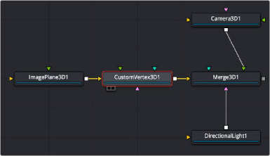
Custom Vertex 3D node manipulating an Image Plane 3D node
Inspector
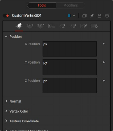
Custom Vertex 3D node Vertex tab
Vertex Tab
Using the fields in the Vertex tab, vertex calculations can be performed on the Position, Normals, Vertex Color, Texture Coordinates, Environment Coordinates, UV Tangents, and Velocity attributes.
The vertices are defined by three XYZ Position values in world space as px, py, pz. Normals, which define as a vector the direction the vertex is pointing as nx, ny, nz.
Vertex color is the Red, Green, Blue, and Alpha color of the point as vcr, vcg, vcb, vca.
![]()
Numbers Tab
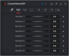
Custom Vertex 3D node Numbers tab
Numbers are variables with a dial control that can be animated or connected to modifiers exactly as any other control might. The numbers can be used in equations on vertices at current time: n1, n2, n3, n4,… or at any time: n1_at(float t), n2_at(float t), n3_at(float t), n4_at(float t), where t is the time you want. The values of these controls are available to expressions in the Setup and Intermediate tabs.
They can be renamed and hidden from the viewer using the Config tab.
Points Tab
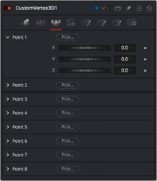
Custom Vertex 3D node Points tab
The point controls represent points in the Custom Vertex 3D tool, not the vertices. These eight point controls include 3D X,Y,Z position controls for positioning points at the current time: (p1x, p1y, p1z, p2x, p2y, p2z) or at any time: p1x_at(float t), p1y_at(float t), p1z_at(float t), p2x_at(float t), p2y_at(float t), p2z_at(float t), where t is the time you want. For example, you can use a point to define a position in 3D space to rotate the vertices around. They can be renamed and hidden from the viewer using the Config tab. They are normal positional controls and can be animated or connected to modifiers as any other node might.
![]()
LUT Tab
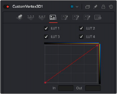
Custom Vertex 3D node LUT tab
The Custom Vertex 3D node provides four LUT splines. A LUT is a lookup table that will
return a value from the height of the LUT spline. For example, getlut1(float x), getlut2(float x),... where x = 0 … 1 accesses the LUT values.
The values of these controls are available to expressions in the Setup and Intermediate tabs using the getlut# function. For example, setting the R, G, B, and A expressions to getlut1(r1), getlut2(g1),
getlut3(b1), and getlut4(a1) respectively, would cause the Custom Vertex 3D node to mimic the Color Curves node.
These controls can be renamed using the options in the Config tab to make their meanings more apparent, but expressions still see the values as lut1, lut2,...lut8.
Setup Tab
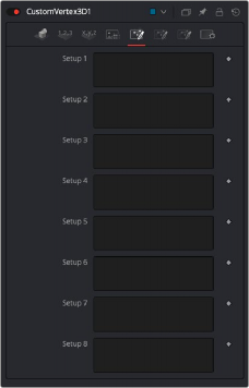
Custom Vertex 3D node Setup tab
![]()
Up to eight separate expressions can be calculated in the Setup tab of the Custom Vertex 3D node. The Setup expressions are evaluated once per frame, before any other calculations are performed. The results are then made available to the other expressions in the node as variables s1, s2, s3, and s4.
Think of them as global setup scripts that can be referenced by the intermediate and channel scripts for each vertex.

NOTE: Because these expressions are evaluated once per frame only and not for each pixel, it makes no sense to use per-pixel variables like X and Y or channel variables like r1, g1, b1, and so on. Allowable values include constants, variables like n1…n8, time, W and H, and so on, and functions like sin() or getr1d().
NOTE: Because these expressions are evaluated once per frame only and not for each pixel, it makes no sense to use per-pixel variables like X and Y or channel variables like r1, g1, b1, and so on. Allowable values include constants, variables like n1…n8, time, W and H, and so on, and functions like sin() or getr1d().
NOTE: Because these expressions are evaluated once per frame only and not for each pixel, it makes no sense to use per-pixel variables like X and Y or channel variables like r1, g1, b1, and so on. Allowable values include constants, variables like n1…n8, time, W and H, and so on, and functions like sin() or getr1d().
For example, Setup scripts can be used to transform vertex from model to world space.
Intermediate Tab
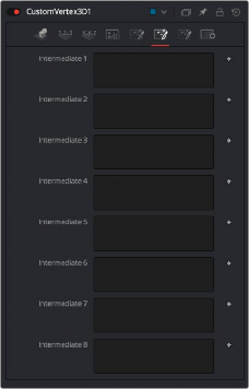
Custom Vertex 3D Node Intermediate tab
An additional eight expressions can be calculated in the Intermediate tab. The Intermediate expressions are evaluated once per vertex, after the Setup expressions are evaluated. Results are available as variables i1, i2, i3, i4, i5, i6, i7, i8, which can be referenced by channel scripts. Think of them as “per vertex setup” scripts.
![]()
For example, you can run the script to produce the new vertex (i.e., new position, normal, tangent, UVs, etc.) or transform from world space back to model space.
Config Tab
Custom Vertex 3D node Config tab
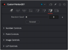
Use this to set the seed for the rand() and rands() functions. Click the Reseed button to set the seed to a random value. This control may be needed if multiple Custom Vertex 3D nodes are required with different random results for each.