< Previous | Contents | Next >
There are eight sets of Number controls, corresponding to the eight sliders in the Numbers tab. Disable the Show Number checkbox to hide the corresponding Number slider, or edit the Name for Number text field to change its name.
There are eight sets of Point controls, corresponding to the eight controls in the Points tab. Disable the Show Point checkbox to hide the corresponding Point control and its crosshair in the viewer.
Similarly, edit the Name for Point text field to change the control’s name.
Common Controls
The Settings tab controls are common to many 3D nodes, and their descriptions can be found in “The Common Controls” section at the end of this chapter.
Displace 3D [3Di]
The Displace 3D node
![]()
Displace 3D Node Introduction
The Displace 3D node is used to displace the vertices of an object along their normals based on a reference image. The texture coordinates on the geometry are used to determine where to sample the image.

TIP: Passing a particle system through a Displace 3D node disables the Always Face Camera option set in the pEmitter. Particles are not treated as point-like objects; each of the four particle vertices are individually displaced, which may or may not be the preferred outcome.
TIP: Passing a particle system through a Displace 3D node disables the Always Face Camera option set in the pEmitter. Particles are not treated as point-like objects; each of the four particle vertices are individually displaced, which may or may not be the preferred outcome.
TIP: Passing a particle system through a Displace 3D node disables the Always Face Camera option set in the pEmitter. Particles are not treated as point-like objects; each of the four particle vertices are individually displaced, which may or may not be the preferred outcome.
When using Displace 3D, keep in mind that it only displaces existing vertices and does not subdivide surfaces to increase detail. To obtain a more detailed displacement, increase the subdivision amount for the geometry that is being displaced. Note that the pixels in the displacement image may contain negative values.
Inputs
The following two inputs appear on the Displace 3D node in the Node Editor:
— SceneInput: The orange scene input is the required input for the Displace 3D node. You use this input to connect another node that creates or contains a 3D scene or object.
— Input: This green input is used to connect a 2D image that is used to displace the object connected to the Scene input. If no image is provided, this node effectively passes the scene straight through to its output. So, although not technically a required input, there isn’t much use for adding this node unless you connect this input correctly.
Basic Node Setup
The output of a Displace 3D node typically connects to a Merge 3D node, integrating it into a larger scene. The 3D geometry you want to displace is connected to the orange input, and in this example, a Fast Noise node is used to displace the geometry.
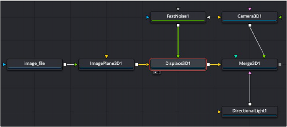
An image on an Image Plane 3D is displaced by a Fast Noise node
![]()
Inspector
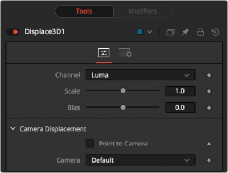
Displace 3D controls
Controls Tab
The Displace 3D Inspector includes two tabs along the top. The primary tab, called the Controls tab, contains the dedicated Displace 3D controls.