< Previous | Contents | Next >
Use the Time Offset slider to offset any animations that are applied to the source geometry. Unlike Time Offset on the Controls tab, Jitter Time Offset is random, based on the Random Seed setting.
Use these three controls to adjust the variation in the translation of the replicated objects.
Use these three controls to adjust the variation in the rotation of the replicated objects.
Use these three controls to adjust the variation in the rotational pivot center of the replicated objects. This affects only the additional jitter rotation, not the rotation produced by the rotation settings in the Controls tab.
Use this control to adjust the variation in the scale of the replicated objects. Uncheck the Lock XYZ checkbox to adjust the scale variation independently on all three axes.
Common Controls
The Settings tab is common to many 3D nodes. The description of these controls can be found in “The Common Controls” section at the end of this chapter.
![]()
Ribbon 3D [3Ri]
The Ribbon 3D node
Ribbon 3D Node Introduction
Ribbon 3D generates an array of subdivided line segments or a single line between two points. It is quite useful for motion graphics, especially in connection with Replicate 3D to attach other geometry to the lines, and with Displace3D for creating lightning bolt-like structures. The array of lines is, by default, assigned with texture coordinates, so they can be used with a 2D texture. As usual, UVMap 3D can be used to alter the texture coordinates. This node relies heavily on certain OpenGL features and does not produce any visible result when the Renderer 3D node is set to use the software renderer.
Furthermore, the way lines are drawn is completely up to the graphics card capabilities, so the ribbon appearance may vary based on your computer’s graphics card.
Inputs
There are two inputs on the Ribbon 3D node: one for the destination geometry that contains the vertices, and one for the 3D geometry you want to replicate.
— 3D Scene: The orange input accepts a 3D scene or geometry.
— Material: The input accepts the 2D texture for the ribbon.
Neither connected input is required.
Basic Node Setup
In the example below, a Ribbon 3D node is used to generate lines. A gradient background is connected to “colorize” the lines. Additional nodes are then used after the Ribbon 3D to bend and distort the lines.
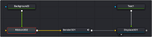
Ribbon 3D generates lines distorted by additional nodes
![]()
Inspector
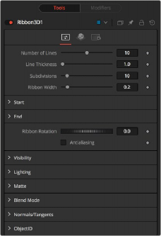
Ribbon 3D controls
Controls Tab
The Controls tab determines the number of ribbon strands, their size, length, and spacing.
The number of parallel lines drawn between the start point and end point.
Line thickness is allowed in the user interface to take on a floating-point value, but some graphics cards allow only integer values. Some cards may only allow lines equal to or thicker than one, or max out at a certain value.
The number of vertices on each line between start point and end points. The higher the number, the more precise and smoother 3D displacement appears.
Determines how far the lines are apart from each other.
XYZ control to set the start point of the ribbon.
XYZ control to set the end point of the ribbon.
Allows rotation of the ribbon around the virtual axis defined by start point and end points.
![]()
Allows you to apply anti-aliasing to the rendered lines. Using anti-aliasing isn’t necessarily recommended. When activated, there may be be gaps between the line segments. This is especially noticeable with high values of line thickness. Again, the way lines are drawn is completely up to the graphics card, which means that these artifacts can vary from card to card.
Common Controls
The controls for Visibility, Lighting, Matte, Blend Mode, Normals/Tangents, and Object ID in the Controls tab are common in many 3D nodes. The Materials tab and Settings tab in the Inspector are also duplicated in other 3D nodes. These common controls are described in detail at the end of this chapter in “The Common Controls” section.