< Previous | Contents | Next >
The Shape 3D node
Shape 3D Node Introduction
The Shape 3D node is used to produce several basic primitive 3D shapes, including planes, cubes, spheres, and cylinders.
Inputs
There are two optional inputs on the Shape 3D. The scene input can be used to combine additional geometry with the Shape 3D, while the material input can be used to texture map the Shape
3D object.
— SceneInput: Although the Shape 3D creates its own 3D geometry, you can use the orange scene input to combine an additional 3D scene or geometry.
— MaterialInput: The green input accepts either a 2D image or a 3D material. If a 2D image is provided, it is used as a diffuse texture map for the basic material built into the node. If a 3D material is connected, then the basic material is disabled.
![]()
Basic Node Setup
In the example below, four Shape 3D nodes are used to create the primitives of a 3D set. Two of the Shape 3D nodes are connected creating a more complex primitive shape. Those shapes can then be used with a Projector 3D to texture them with a realistic material.
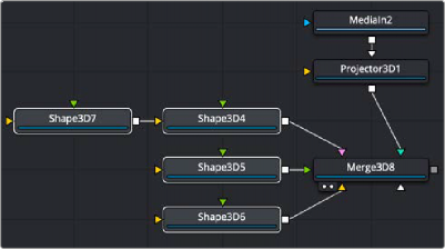
Shape 3D nodes combined with Projector 3D to create a realistic 3D set
Inspector
Shape 3D controls
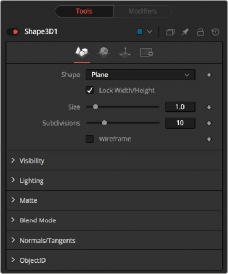
Controls Tab
The Controls tab allows you to select a shape and modify its geometry. Different controls appear based on the specific shape that you choose to create.
This menu allows you to select the primitive geometry produced by the Shape 3D node. The remaining controls in the Inspector change to match the selected shape.
![]()
— Lock Width/Height/Depth: [plane, cube] If this checkbox is selected, the width, height, and depth controls are locked together as a single size slider. Otherwise, individual controls over the size of the shape along each axis are provided.
— Size Width/Height/Depth: [plane, cube] Used to control the size of the shape.
When Cube is selected in the shape menu, the Cube uses cube mapping to apply the Shape node’s texture (a 2D image connected to the material input on the node).
When a Sphere, Cylinder, Cone, or Torus is selected in the shape menu, this control sets the radius of the selected shape.
When a cone is selected in the Shape menu, this control is used to define a radius for the top of a cone, making it possible to create truncated cones.
When the Sphere, Cylinder, Cone, or Torus shape is selected in the Shape menu, this range control determines how much of the shape is drawn. A start angle of 180° and end angle of 360° would only draw half of the shape.
When a Sphere or Torus is selected in the Shape menu, this range control is used to crop or slice the object by defining a latitudinal subsection of the object.
When Cylinder or Cone is selected in the Shape menu, the Bottom Cap and Top Cap checkboxes are used to determine if the end caps of these shapes are created or if the shape is left open.
When the Torus is selected in the Shape menu, Section controls the thickness of the tube making up the torus.
The Subdivision controls are used to determine the tessellation of the mesh on all shapes. The higher the subdivision, the more vertices each shape has.
Enabling this checkbox causes the mesh to render only the wireframe for the object.
Common Controls
The controls for Visibility, Lighting, Matte, Blend Mode, Normals/Tangents, and Object ID in the Controls tab are common in many 3D nodes. The Materials tab, Transforms tab, and Settings tab in the Inspector are also duplicated in other 3D nodes. These common controls are described in detail at the end of this chapter in “The Common Controls” section.
Sphere Map vs. Connecting the Texture to a Sphere Directly
![]()
You can connect a LatLong (equirectangular) texture map directly to a sphere instead of piping it through the Sphere Map node first. This results in a different rendering if you set the start/end angle and latitude to less than 360°/180°. In the first case, the texture is squashed. When using the Sphere Map node, the texture is cropped. Compare:
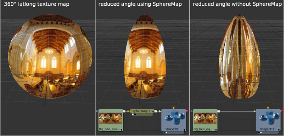
Spherical mapping differences

NOTE: If you pipe the texture directly into the sphere, it is also mirrored horizontally. You can change this by using a Transform node first.
NOTE: If you pipe the texture directly into the sphere, it is also mirrored horizontally. You can change this by using a Transform node first.
NOTE: If you pipe the texture directly into the sphere, it is also mirrored horizontally. You can change this by using a Transform node first.