< Previous | Contents | Next >
The Settings tab in the Inspector is duplicated in other 3D nodes. These common controls are described in detail at the end of this chapter in “The Common Controls” section.
Weld 3D [3We]
The Weld 3D node
Weld 3D Node Introduction
Sometimes 3D geometry has vertices that should have been joined when the geometry was created, but for one reason or another they are not joined. This can cause artifacts, especially when the two vertices have different normals.
For example, you may find:
— The different normals produce hard shading/lighting edges where none were intended.
— If you try to Displace 3D the vertices along their normals, they crack.
— Missing pixels or doubled-up pixels in the rendered image.
![]()
— Particles pass through the tiny invisible cracks.
Instead of round tripping back to your 3D modeling application to fix the “duplicated” vertices, the Weld 3D node allows you to do this in Fusion. Weld 3D welds together vertices with the same or nearly the same positions. This can be used to fix cracking issues when vertices are displaced by welding the geometry before the Displace. There are no user controls to pick vertices. Currently, this node welds together just position vertices; it does not weld normals, texcoords, or any other vertex stream. So, although the positions of two vertices have been made the same, their normals still have their old values. This can lead to hard edges in certain situations.
Inputs
The Weld 3D node has a single input for a 3D scene or 3D object you want to repair.
— Scene Input: The orange scene input is connected to the 3D scene or 3D object you want to fix.
Basic Node Setup
The Weld 3D node is placed after the geometry that has duplicate vertices problems. Sometimes problems are exposed when displacing the geometry. In that case, placing the weld after the geometry but before the Displace 3D can repair the issues.
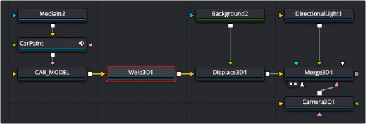
Weld 3D is placed after the 3D geometry that needs repair
Inspector
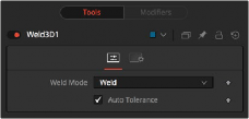
Weld 3D controls
![]()
Controls Tab
The Controls tab for the Weld 3D node includes a simple Weld Mode menu. You can choose between welding vertices or fracturing them.
Fracturing is the opposite of welding, so all vertices are unwelded. This means that all polygon adjacency information is lost. For example, an Image Plane 3D normally consists of connected quads that share vertices. Fracturing the image plane causes it to become a bunch of unconnected quads.
In auto mode, the Tolerance value is automatically detected. This should work in most cases. It can also be adjusted manually if needed.

USAGE Use Weld 3D when issues occur with the geometry. Don’t use it everywhere just because it’s there, as it influences render time.
Weld 3D is intended to be used as a mesh robustness tool and not as a mesh editing tool to merge vertices. If you can see the gap between the vertices you want to weld in the 3D view, you are probably misusing Weld 3D. Unexpected things may happen when you do this; do so at your own peril.
LIMITATIONS Setting the tolerance too large can cause edges/faces to collapse to points.
If your model has detail distributed over several orders of scale, picking a tolerance value can be hard or impossible.
For example, suppose you have a model of the International Space Station and there are lots of big polygons and lots of really tiny polygons. If you set the tolerance too large, small polygons that shouldn’t merge do; if you set the tolerance too small, some large polygons won’t be merged.
Vertices that are far from the origin can fail to merge correctly. This is because bignumber
+ epsilon can exactly equal bignumber in float math. This is one reason it may be best to merge in local coordinates and not in world coordinates.
Sometimes Weld 3D-ing a mesh can make things worse. Take Fusion’s cone, for instance. The top vertex of the cone is currently duplicated for each adjoining face, and they all have different normals. If you weld the cone, the top vertices merge and only have one normal, making the lighting look weird.
Weld 3D is not multithreaded.

WARNING Do not misuse Weld 3D to simplify (reduce the polygon count of) meshes. It is designed to efficiently weld vertices that differ by only very small values, like a
0.001 distance.
WARNING Do not misuse Weld 3D to simplify (reduce the polygon count of) meshes. It is designed to efficiently weld vertices that differ by only very small values, like a
0.001 distance.
WARNING Do not misuse Weld 3D to simplify (reduce the polygon count of) meshes. It is designed to efficiently weld vertices that differ by only very small values, like a
0.001 distance.
![]()
Common Controls
The Settings tab in the Inspector is duplicated in other 3D nodes. These common controls are described in detail at the end of this chapter in “The Common Controls” section.