< Previous | Contents | Next >
The Spot Light node
Spot Light Node Introduction
A spotlight is a light that comes from a specific point and that has a clearly defined cone, with falloff of the light to the edges. Experienced stage and theatre lighting technicians may recognize the spotlight as being very similar to practical lights used in live productions. This is the only type of light capable of casting shadows.
Similar to a Camera 3D, you connect lights into a Merge 3D and view them in the scene by viewing the Merge 3D node. Selecting a light node and loading it into the viewer does not show anything.
Inputs
The Spot Light node includes a single optional orange input for a 3D scene or 3D geometry.
— SceneInput: The orange input is an optional input that accepts a 3D scene. If a scene is provided, the Transform controls in this node apply to the entire scene provided.
Basic Node Setup
![]()
The Spot Light node is designed to be part of a larger 3D scene. You connect the light directly into a Merge 3D. Separating lights into different Merge 3D nodes allows you to control which lights affect which objects.
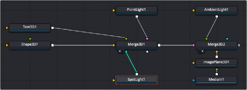
Spot Light node structure
Inspector
Spot Light control
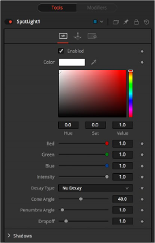
Controls Tab
The Controls tab is used to set the color and brightness of the spotlight. The position, rotation, and distance of the light source are controlled in the Transform tab.
![]()
When the Enabled checkbox is turned on, the spotlight affects the scene. When the checkbox is turned off the light is turned off. This checkbox performs the same function as the red switch to the left of the node’s name in the Inspector.
Use this standard Color control to set the color of the light.
Use this slider to set the Intensity of the spot light. A value of 0.2 indicates 20% percent light.
A spotlight defaults to No Falloff, meaning that its light has equal intensity on geometry despite the distance from the light to the geometry. To cause the intensity to fall off with distance, set the Decay type to either Linear or Quadratic modes.
The Cone Angle of the light refers to the width of the cone where the light emits its full intensity. The larger the angle, the wider the cone angle, up to a limit of 90 degrees.
The Penumbra Angle determines the area beyond the cone angle where the light’s intensity falls off toward 0. A larger penumbra angle defines a larger falloff, while a value of 0 generates a hard- edged light.
The Dropoff controls how quickly the penumbra angle falls off from full intensity to 0.
Shadows
This section provides several controls used to define the shadow map used when this spotlight creates shadows. For more information, see Chapter 85, “3D Compositing Basics,” in the DaVinci Resolve Reference Manual, or Chapter 23 in the Fusion Reference Manual.
The Enable Shadows checkbox should be selected if the light is to produce shadows. This defaults to selected.
Use this standard Color control to set the color of the shadow. This defaults to black (0, 0, 0).
The shadow density determines the transparency of the shadow. A density of 1.0 produces a completely opaque shadow, whereas lower values make the shadow more transparent.
The Shadow Map Size control determines the size of the bitmap used to create the shadow map. Larger values produce more detailed shadow maps at the expense of memory and performance.
![]()
Shadow Map Proxy determines the size of the shadow map used when the Proxy or Auto Proxy modes are enabled. A value of 0.5 would produce a shadow map at half the resolution defined in the Shadow Map Size.
Shadows are essentially textures applied to objects in the scene, so there is occasionally Z-fighting, where the portions of the object that should be receiving the shadows render over the top of the shadow. Biasing works by adding a small depth offset to move the shadow away from the surface it is shadowing, eliminating the Z-fighting. Too little bias and the objects can self-shadow themselves. Too much bias and the shadow can become separated from the surface. Adjust the Multiplicative Bias first, and then fine tune the result using the Additive Bias control.
For more information, see the Multiplicative and Additive Bias section of Chapter 85, “3D Compositing Basics,” in the DaVinci Resolve Reference Manual, or Chapter 25 in the Fusion Reference Manual.
Normally, an RGBAZ shadow map is used when rendering shadows. By enabling this option, you are forcing the renderer to use a Z-only shadow map. This can lead to significantly faster shadow rendering while using a fifth as much memory. The disadvantage is that you can no longer cast “stained glass”-like shadows.
Sets the quality for sampling of the shadow map.
NOTE: Shadows have a hard edge. No filtering of the shadow map is done at all. The advantage of this method is that you only have to sample one pixel in the shadow map, so it is fast.
NOTE: Shadows have a hard edge. No filtering of the shadow map is done at all. The advantage of this method is that you only have to sample one pixel in the shadow map, so it is fast.
NOTE: Shadows have a hard edge. No filtering of the shadow map is done at all. The advantage of this method is that you only have to sample one pixel in the shadow map, so it is fast.
Soft edges in shadows are produced by filtering the shadow map when it is sampled. Fusion provides two separate filtering methods for rendering shadows, which produce different effects.
— Constant: Shadows edges have a constant softness. A filter with a constant width is used when sampling the shadow map. Adjusting the Constant Softness slider controls the size of the filter. Note that the larger you make the filter, the longer it takes to render the shadows.
— Variable: The shadow edge softness grows the further the shadow receiver is positioned from the shadow caster. The variable softness is achieved by changing the size of the filter based on the distance between the receiver and caster. When this option is selected, the Softness Falloff, Min Softness, and Max Softness sliders appear.
If the Softness is set to Constant, then this slider appears. It can be used to set the overall softness of the shadow.
![]()
The Softness Falloff slider appears when the Softness is set to variable. This slider controls how fast the softness of shadow edges grows with distance. More precisely, it controls how fast the shadow map filter size grows based upon the distance between the shadow caster and receiver. Its effect is mediated by the values of the Min and Max Softness sliders.
The Min Softness slider appears when the Softness is set to Variable. This slider controls the Minimum Softness of the shadow. The closer the shadow is to the object casting the shadow, the sharper it is, up to the limit set by this slider.
The Max Softness slider appears when the Softness is set to Variable. This slider controls the Maximum Softness of the shadow. The further the shadow is from the object casting the shadow, the softer it is, up to the limit set by this slider.
Common Controls
The options presented in the Transform and Settings tabs are commonly found in other lighting nodes. For more detailed information on the controls found in these tabs, see “The Common Controls” section at the end of this chapter.