< Previous | Contents | Next >
The Texture 2D node
Texture Node Overview
NOTE: Background pixels may have U and V values of 0.0, which set those pixels to the color of the texture’s corner pixel. To restrict texturing to specific objects, use an effect mask based on the Alpha of the object, or its Object or Material ID channel. For more information, see Chapter 78, “Understanding Image Channels,” in the DaVinci Resolve Reference Manual, or Chapter 16 in the Fusion Reference Manual.
NOTE: Background pixels may have U and V values of 0.0, which set those pixels to the color of the texture’s corner pixel. To restrict texturing to specific objects, use an effect mask based on the Alpha of the object, or its Object or Material ID channel. For more information, see Chapter 78, “Understanding Image Channels,” in the DaVinci Resolve Reference Manual, or Chapter 16 in the Fusion Reference Manual.
NOTE: Background pixels may have U and V values of 0.0, which set those pixels to the color of the texture’s corner pixel. To restrict texturing to specific objects, use an effect mask based on the Alpha of the object, or its Object or Material ID channel. For more information, see Chapter 78, “Understanding Image Channels,” in the DaVinci Resolve Reference Manual, or Chapter 16 in the Fusion Reference Manual.
The Texture 2D node sets metadata of an image being used for a texture map. By default, an image will be (0,0) to (1,1) UV, but that can be changed. The Texture node relies on the presence of U and V Map channels in 3D rendered images. If these channels are not present, this node has no effect.
Inputs
— Image Input: The orange image input expects a 2D image.
![]()
Basic Node Setup
The Texture 2D node below takes a 2D gradient from the Background node and sets the UV metadata for it. The texture is then applied to the FBX geometry based on that metadata. If you have the option to use the UV Map tool, it is recommended because it may be faster and has onscreen controls.
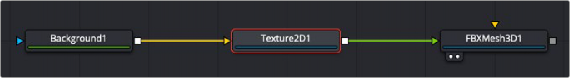
A Texture 2D node is used to set the 3D texture metadata for the input image.
Inspector
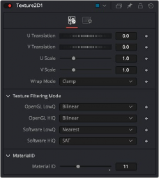
Texture 2D controls
Controls Tab
The Controls tab of the Inspector includes the following options.
These sliders can be used to offset the texture along the U and V coordinates.
These sliders can be used to scale the texture along the U and V coordinates.
![]()
If a texture is transformed in the texture space (using the controls below or the UV Map node), then it’s possible that areas beyond the image borders will be mapped on the object. The Wrap Mode determines how the image is applied in these areas.
— Wrap: This wraps the edges of the image around the borders of the image.
— Clamp: The color at the edges of the images is used for texturing. This mode is similar to the Duplicate mode in the Transform node.
— Black: The image is clipped along its edges. A black color with Alpha = 0 is used instead.
— Mirror: The image is mirrored in both X and Y.
The texture can be filtered differently depending on whether you are using the Software Renderer or OpenGL renderer in the Renderer 3D node. Within the two render engines, you can choose between high-quality anti-aliasing or low quality. The texture filtering mode provides different filtering options for the two render engines and the two anti-aliasing settings.
— Nearest: The simplest filtering technique is very fast but can cause artifacts when scaling textures.
— Bilinear: A standard isotropic filtering technique for scaling textures into multiple resolutions. Works well for magnification of textures.