< Previous | Contents | Next >
— Repeat: When using the Gradient Offset control to shift the gradient, the border colors wrap around. Shifting the default gradient to the left results in a sharp jump from white to black, while shifting it to the right results in a sharp jump from black to white.
— Ping Pong: When using the Gradient Offset control to shift the gradient, the border colors ping- pong back and forth. Shifting the default gradient to the left results in the edge fading from white back to black, while shifting it to the right results in the edge fading from black back to white.
Determines the accuracy with which the gradient is created.
This slider sets the numeric identifier assigned to this material. This value is rendered into the MatID auxiliary channel if the corresponding option is enabled in the renderer.
Common Controls
The Settings tab in the Inspector is duplicated in other 3D nodes. These common controls are described in detail at the end of this chapter in “The Common Controls” section.
Sphere Map [3SpM]
![]()
The SphereMap node
Sphere Map Node Overview
The Sphere Map node can be used to create simulated environment mapping, also called reflection mapping. Ray trace rendering a reflective scene can be very time consuming, but sphere map- based reflection mapping can generate 360-degree reflections faster with little loss of accuracy. For example, when creating a reflective environment, a sphere map is created, large enough to surround the 3D object in your scene. The sphere is mapped with the environment you want reflected and connected to the Reflection Color input on a Reflect node.
Inputs
The single image input on the Sphere Map node accepts a 2D image texture in an equirectangular format (where the X-axis represents 0–360 degrees longitude, and the Y-axis represents –90 to +90 degrees latitude.)
— ImageInput: The orange Image input accepts a 2D RGBA image. Preferably, this is an equirectangular image that shows the entire vertical and horizontal angle of view up to 360 degrees.
Basic Node Setup
The Sphere Map node below is mapped with a spherical image to generate the environment reflected on the Shape 3D. It is connected to the Reflection Color input on a Reflect node.
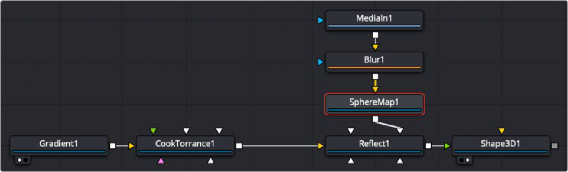
A Sphere Map node generates a reflective environment when connected to a Reflect node Reflection Color input.
Inspector
![]()
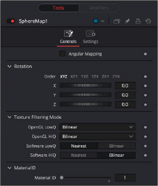
Sphere Map controls
Controls Tab
The Controls tab in the Inspector modifies the mapping of the image input to the sphere map.
Adjusts the texture coordinate mapping so the poles are less squashed and areas in the texture get mapped to equal areas on the sphere. It turns the mapping of the latitude lines from a hemispherical fisheye to an angular fisheye. This mapping attempts to preserve area and makes it easier to paint on or modify a sphere map since the image is not as compressed at the poles.
Offers controls to rotate the texture map.
This slider sets the numeric identifier assigned to this material. This value is rendered into the MatID auxiliary channel if the corresponding option is enabled in the renderer.
The node expects an image with an aspect ratio of 2:1. Otherwise, the image is clamped according to the following rules:
— 2 * width > height: The width is fitted onto the sphere, and the poles display clamped edges.
— 2 * width < height: The height is fitted onto the sphere, and there is clamping about the 0-degree longitude line.
Common Controls
The Settings tab in the Inspector is duplicated in other 3D nodes. These common controls are described in detail at the end of this chapter in “The Common Controls” section.
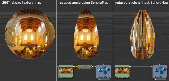
Sphere Map vs. Connecting the Texture to a Sphere Directly
![]()
You can connect an equirectangular texture map directly to a sphere instead of piping it through the Sphere Map node first. This results in a different rendering if you set the start/end angle and latitude to less than 360°/180°. In the first case, the texture is squashed. When using the Sphere Map node, the texture is cropped. Compare:

NOTE: If you pipe the texture directly into the sphere, it is also mirrored horizontally. You can change this by using a Transform node first.
NOTE: If you pipe the texture directly into the sphere, it is also mirrored horizontally. You can change this by using a Transform node first.
NOTE: If you pipe the texture directly into the sphere, it is also mirrored horizontally. You can change this by using a Transform node first.
Spherical mapping differences