< Previous | Contents | Next >
— The Saturation Knee slider sets the image level at which saturation mapping begins. Below this level, no remapping is applied. All saturation values from this level on up are remapped according to the Saturation Max. slider. A value of 1.0 is maximum saturation in the currently selected output color space.
— The Saturation Max. slider sets the new maximum level to which you want to either raise or lower all saturation values that are above the Saturation Knee setting. A value of 1.0 is maximum saturation in the currently selected output color space.
— Apply Forward OOTF: Check this box to convert the image from scene referred to display referred color management.
— Apply Inverse OOTF: Check this box to convert the image from display referred to scene referred color management.
Common Controls
The Settings tab in the Inspector is also duplicated in other Color nodes. These common controls are described in detail at the end of this chapter in “The Common Controls” section.
Revival
A sub category of the Color tools in Fusion that pertains to fixing common technical errors with programs being finished, remastered, or restored.
![]()
Chromatic Aberration Removal [CAr]
The Chromatic Aberration Removal node
Chromatic Aberration Removal Node Introduction
A node that lets you manually correct the slight color fringing that results from chromatic aberration in a lens. Show Estimated Fringes checkboxes for the RGB channels display an “alignment guide” that visually isolates each of the types of fringing against gray.
Inputs
The two inputs on the Chromatic Aberration Removal node are the input and effect mask.
— Input: The orange input connects the primary 2D image for the auto gain.
— Effect Mask: The blue input is for a mask shape created by polylines, basic primitive shapes, paint strokes, or bitmaps from other tools. Connecting a mask to this input limits the adjustment to only those pixels within the mask. An effect mask is applied to the tool after the tool is processed.
Basic Node Setup
The Chromatic Aberration Removal node, like many 2D image-processing nodes, receives a 2D image, such as a Loader node or the MediaIn1 shown below. The output continues the node tree by connecting to another 2D image-processing node or a Merge node.
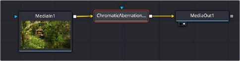
A Chromatic Aberration Removal node applied to a MediaIn1 node
![]()
Inspector
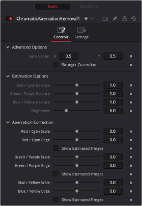
Chromatic Aberration Removal controls
Controls Tab
The Controls tab contains the primary controls necessary for adjusting the Chromatic Aberration Removal parameters.
Advanced Options provide additional parameters for problem shots.
— – Lens Center: Center X and Y parameters let you offset the center of the lens if you’re dealing with a reframed and re-rendered shot.
— – Stronger Correction: Shows the location of image features that resemble fringing.
The Estimation Options are used solely to highlight and identify areas of fringing. They do not affect the final output of the image. They only become available when one of the Show Estimated Fringes boxes is checked in the Aberration Correction section.
— – R/C, G/P, B/Y Balance: These tools adjust the incoming balance between their respective colors to better identify hard to see fringing.
— – Brightness: Magnifies the fringe indicators that are displayed when you turn on either of the Estimated Fringes checkboxes
These tools let you make manual adjustments to correct aberration issues.
— – R/C, G/P, B/Y Scale: Adjust these sliders to eliminate the fringing from their respective colors.
— – R/C, G/P, B/Y Edge: Adjusts to compensate for the difference in fringing due to the curvature of the lens’ edges
![]()
— – Show Estimated Fringes: Checking this box will show just the estimated fringes over a gray background. It will also activate the Estimation Options sliders, which will let you further highlight and identify areas of fringing.
This makes it easy to make manual adjustments to correct the problem, using the Scale and Edge controls to individually adjust Red/Cyan, Green/Purple, and Blue/Yellow fringing.
Common Controls
The Settings tab in the Inspector is also duplicated in other Color nodes. These common controls are described in detail at the end of this chapter in “The Common Controls” section.